Plasma doping method
A plasma and plasma source technology, applied in the field of plasma doping, can solve the problems of large dispersion of emitted waves, poor controllability and reproducibility of doping concentration, etc., and achieve the effect of stable low-concentration doping
- Summary
- Abstract
- Description
- Claims
- Application Information
AI Technical Summary
Problems solved by technology
Method used
Image

Examples
Embodiment 1
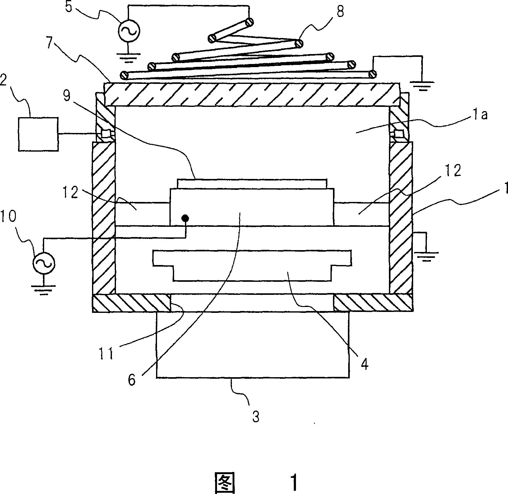
[0056] Hereinafter, a plasma doping method according to Embodiment 1 of the present invention will be described with reference to FIG. 1 .
[0057] FIG. 1 is a cross-sectional view of a plasma doping apparatus used for doping by a plasma doping method according to Embodiment 1 of the present invention. In FIG. 1 , a predetermined gas is supplied from a gas supply device 2 into an inner space 1 a of a vacuum vessel 1 and exhausted by a turbo molecular gas pump 3 as an exhaust device. The internal space 1a of the vacuum container 1 is kept at a predetermined pressure by the pressure regulating valve 4, and at the same time, a high frequency of 13.56 MHz is supplied from the high-frequency power supply 5 to the helical coil 8 provided near the dielectric window 7 facing the sample electrode 6. frequency power. As a result, inductively coupled plasma is generated in the internal space 1 a of the vacuum vessel 1 , and the plasma doping process can be performed on the silicon subst...
Embodiment 2
[0064] Next, a plasma doping method according to Embodiment 2 of the present invention will be described with reference to FIG. 1 as in Embodiment 1. FIG. The matters described in Embodiment 1 in FIG. 1 are also referred to Embodiment 2 in the same manner.
[0065] The structure and basic operation of the plasma doping device in FIG. 1 have been described in detail in the above-mentioned embodiment 1 of the present invention, so repeated descriptions are omitted.
[0066] In FIG. 1 , after placing the silicon substrate 9 on the sample electrode 6, while maintaining the temperature of the sample electrode 6 at 10° C., argon gas was introduced into the vacuum vessel 1 at 50 sccm and acetonitrile as a doping source gas was input at 3 sccm. Borane (B 2 h 6 )gas. While controlling the pressure in the vacuum vessel 1 to a first pressure of 0.8 Pa, 800 W of high-frequency power was supplied to the coil 8 serving as a plasma source to generate plasma in the vacuum vessel 1 . One s...
Embodiment 3
[0072] Next, a plasma doping method according to Embodiment 3 of the present invention will be described with reference to FIG. 1 as in Embodiment 1. FIG. The matters described in Embodiment 1 in FIG. 1 are also referred to Embodiment 3 in the same manner.
[0073] The structure and basic operation of the plasma doping device in FIG. 1 have been described in detail in the above-mentioned embodiment 1 of the present invention, so repeated descriptions are omitted.
[0074] In FIG. 1 , after placing the silicon substrate 9 on the sample electrode 6, while keeping the temperature of the sample electrode 6 at 10° C., helium gas and 3 sccm of helium gas as the dopant source gas were introduced into the vacuum vessel 1 at 50 sccm. Diborane (B 2 h 6 )gas. While controlling the pressure in the vacuum vessel 1 to a first pressure of 3 Pa, 100 W of high-frequency power was supplied to the coil 8 serving as a plasma source to generate plasma in the vacuum vessel 1 . After 1 second of...
PUM
 Abstract
Description
Claims
Application Information
 - R&D
- Intellectual Property
- Life Sciences
- Materials
- Tech Scout
- Unparalleled Data Quality
- Higher Quality Content
- 60% Fewer Hallucinations
Browse by: Latest US Patents, China's latest patents, Technical Efficacy Thesaurus, Application Domain, Technology Topic, Popular Technical Reports.
© 2025 PatSnap. All rights reserved.Legal|Privacy policy|Modern Slavery Act Transparency Statement|Sitemap|About US| Contact US: help@patsnap.com