Voluminous defect free non-crystal alloy antigravity casting method and special purpose die

An anti-gravity casting and amorphous alloy technology, which is applied in the direction of manufacturing tools, casting equipment, and equipment for feeding molten metal into molds, etc., can solve the problems of poor mechanical properties of amorphous and nanocrystalline alloys and the formation of flow marks. Achieve the effect of ensuring the surface finish of the alloy, avoiding gas flow marks, and ensuring the cooling rate of solidification

Inactive Publication Date: 2008-02-13
BEIHANG UNIV
View PDF0 Cites 2 Cited by
  • Summary
  • Abstract
  • Description
  • Claims
  • Application Information

AI Technical Summary

Problems solved by technology

Water quenching method, suction casting method, spray casting method, high pressure casting method and other methods have different limitations due to mold or equipment limitations
The pouring method adopts gravity direction casting, that is, the melt flow direction is consistent with the gravity direction and the melt flow direction is opposite to the gas discharge direction. It is easy to cause residual gas in the casting during the rapid solidification process to form pores and form flow marks on the surface of the casting. , experiments have shown that the mechanical properties of amorphous nanocrystalline alloys prepared by this method are significantly worse in the above two regions

Method used


Image

  • Voluminous defect free non-crystal alloy antigravity casting method and special purpose die

Examples


Embodiment 1

[0019] The Zr-Al-Ni-Cu master alloy is configured according to the atomic percentage: Zr 55 -Al 10 -Ni 5 -Cu 30 , melting in a high-frequency induction furnace in a vacuum state, and casting under the protection of an inert gas, the specific steps are:

[0020] 1. Assign Zr according to atomic percentage 55 al 10 Ni 5 Cu 30 The master alloy is coarsely crushed and put into a quartz crucible for casting, the quartz crucible containing the master alloy is placed in a high-frequency induction furnace, and the copper mold for rapid solidification is placed in a vacuum cavity, located in the quartz the lower end of the crucible;

[0021] 2. Pre-adjust the position of the casting nozzle of the quartz crucible and the sprue cup of the copper mold to ensure that the molten alloy completely flows into the copper mold during the casting process;

[0022] 3. Close the furnace door of the vacuum furnace body and evacuate to 5×10 -3 Pa, filled with argon for protection;

[0023] ...

Embodiment 2

[0026] The difference from Example 1 is:

[0027] The alloy smelting and pouring method is the same as in Example 1. The sprue cup of the copper mold and the vertical sprue are socketed with the thermal insulation graphite tube, and the molten alloy is filled to the mold through the thermal insulation graphite tube, ensuring that the alloy in the sprue and the vertical sprue will not be caused by The copper mold is rapidly cooled and solidified, thereby ensuring the integrity of the mold filling.

Embodiment 3

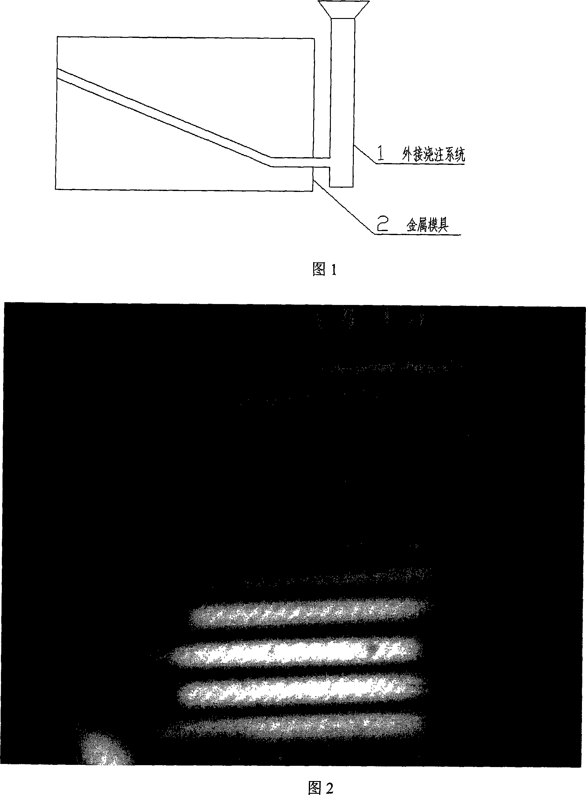
[0029] The alloy smelting and pouring method is the same as in Example 1. The sprue cup and the vertical sprue are graphite external parts connected to the copper mold (as shown in Figure 2). The molten alloy flows against the direction of gravity through the external gating system and fills the copper mold after casting. Rapid solidification forms completely bulk amorphous.


PUM


Abstract

The present invention relates to a large flawless amorphous alloy antigravity casting method and a special mold. The master alloy is heated until the temperature is higher than that with which the alloy melts and infused into a special mold used for fast cooling; the alloy flows from the bottom of the mold in the antigravity direction to fill the casting mold; the casting mold is a bottom pour and open one and the included angle between the central line of the casting mold and the vertical direction is greater than 0 and smaller than or equal to 90 degrees; the casting mold upper end is equipped with an air outlet groove which is communicated with the outside. With the present invention, the alloy flowing direction is the same as that of the air exhaust which is beneficial to producing large flawless plate or bar made of amorphous, nanocrystal and the compound materials or casts of complicated structure. The inside and surface of the produced sample do not have the flaw of air hole which increases the alloy density and surface finish.

Description

technical field [0001] The invention relates to an amorphous alloy preparation technology, in particular to a large-volume defect-free amorphous alloy anti-gravity casting method and a special mold. Background technique [0002] Bulk amorphous alloys are prepared by rapid cooling after melting the master alloy. Generally, methods for preparing bulk amorphous alloys include water quenching, suction casting, spray casting, high pressure casting and pouring. Water quenching method, suction casting method, spray casting method, high pressure casting method and other methods all have different limitations due to mold or equipment limitations. The pouring method adopts gravity direction casting, that is, the melt flow direction is consistent with the gravity direction and the melt flow direction is opposite to the gas discharge direction. It is easy to cause residual gas in the casting during the rapid solidification process to form pores and form flow marks on the surface of the ...

Claims


Application Information

Patent Timeline
IPC IPC(8): B22D27/20B22D35/02
Inventor 张涛李岩黄东亚逄淑杰马朝利
Owner BEIHANG UNIV
Why Eureka
Try Eureka