Reinforcing phase metallic gradient composite material manufacturing process and equipment thereof

A composite material and manufacturing process technology, which is applied in the field of reinforced phase metal gradient composite material manufacturing process and equipment, can solve the problems of inability to manufacture alloy layer composite products, slow cooling rate of matrix materials, and limited application fields, so as to reduce the size of the outer two. Secondary heating process, avoid internal inclusions and pores, and improve product quality

Active Publication Date: 2008-03-05
丁家伟 +1
View PDF0 Cites 43 Cited by
  • Summary
  • Abstract
  • Description
  • Claims
  • Application Information

AI Technical Summary

Problems solved by technology

Although this process has many advantages compared with the sand casting process, the lost foam casting method also has some disadvantages. Because the alloy paste block and the foam plastic model are put together during the molding, the reinforcement cannot be formed before pouring. Preheating makes it impossible to manufacture composite products with a thicker alloy layer, so that the parts

Method used


Image

  • Reinforcing phase metallic gradient composite material manufacturing process and equipment thereof
  • Reinforcing phase metallic gradient composite material manufacturing process and equipment thereof
  • Reinforcing phase metallic gradient composite material manufacturing process and equipment thereof

Examples


Embodiment 1

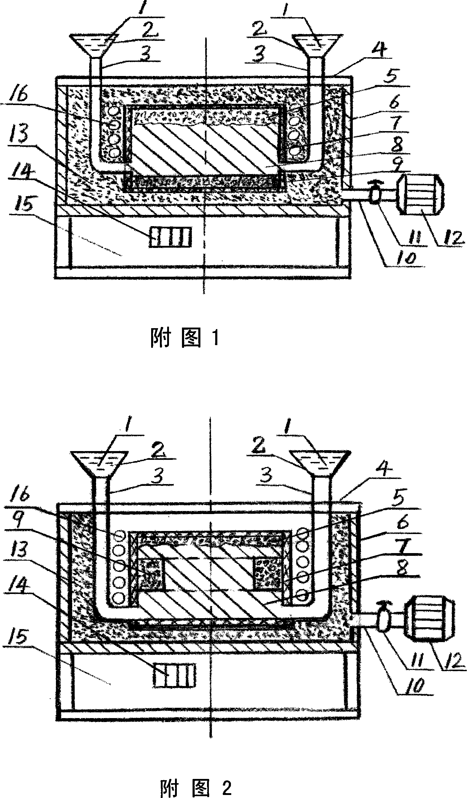
[0018] Embodiment 1: In Figure 1, the equipment has a workbench 15, a flask 6 is installed on the workbench 15, a flask cover 4 is installed on the flask 6, and a flask cover 4 is installed on either side of the flask 6. There is a vacuum pipe 10, which is connected with a control valve 11 and a vacuum pump 12. An electromagnetic induction heater 16 is installed outside the model 5 in the sand box 6, and an electric vibrator 14 is installed on the workbench 15. A pouring funnel 2 is installed on the upper part or side of the sand mold 6 or the sand mold 6, and a pouring runner 3 is connected under the pouring funnel 2.

[0019]At the beginning of the work, first mix reinforced particles or reinforced short fibers or solid self-lubricating materials or boron-containing self-fluxing alloys with special properties such as binders and solvents, or combine various strong carbides and nitrides to form elemental alloys The powder is mixed with carbon powder, nitrogen-containing alloy and...

Embodiment 2

[0020] Embodiment 2: In Figure 2, the difference from Figure 1 is that the alloy paste block 9 is fixed in the middle of the polystyrene foam model 5. Repeating the composite process of embodiment 1 can be manufactured in the middle of the composite material A functionally gradient composite material 8 or a casting product 8 of a large thickness alloy layer containing an alloy layer material. Other processes and equipment are the same as in Embodiment 1, omitted.

Embodiment 3

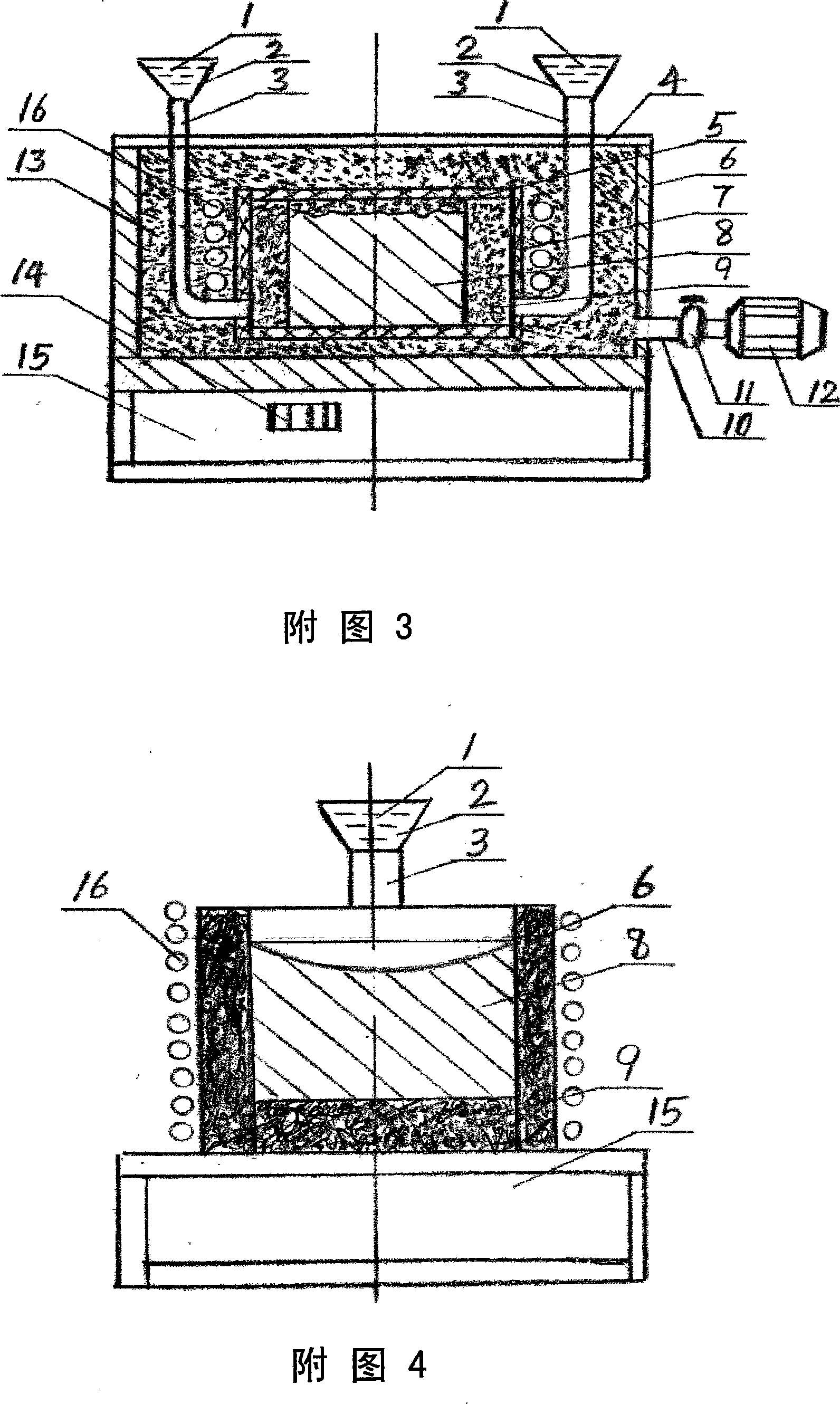
[0021] Example 3: In Figure 3, the difference from Figure 1 is that the alloy paste block 9 is fixed on the entire outer surface of the polystyrene foam model 5. Repeating the composite process of Example 1 can be made into composite materials. The entire outer surface contains a functionally gradient composite material 8 or a casting product 8 with a large thickness of the alloy layer material. Other processes and equipment are the same as in Embodiment 1, omitted.


PUM


Abstract

The present invention discloses process and apparatus for preparing composite material with gradient reinforcing phase. The composite material is prepared through fixing reinforcing alloy blocks in the required positions of the foamed plastic model, vacuum vibrating molding, heating the alloy blocks to 100-1200 deg.c with one outside electromagnetic induction heater, pouring base metal liquid, which infiltrates into the gaps of alloy powder to form great thickness gradient alloy layer with special function in the required positions of the base metal. The process has only once heating, no oxidation of the reinforcing alloy material, and raised flowability and permeability of the metal liquid, and is suitable for thick casting with two phases of different materials in high combination strength and high quality.

Description

Technical field [0001] The present invention belongs to the technical field of surface gradient composite materials, and mainly relates to a manufacturing process and equipment of a reinforced phase metal gradient composite material. Background technique [0002] Gradient composite materials are based on the requirements of use, select two materials with different properties, and adopt various composite technologies to make the composition and structure of the middle part continuously change in a gradient without obvious internal interfaces, so that the material properties and functions are along the thickness A new type of composite material with a gradient change in direction. Its remarkable feature is that it overcomes the performance mismatch problem of the combination of the two materials, and makes the two sides of the material have different functions. The material is now widely used in aviation industry, aerospace industry, nuclear energy technology, electronics, optics, ...

Claims


Application Information

Patent Timeline
IPC IPC(8): B22D19/14
Inventor 丁家伟丁刚
Owner 丁家伟
Why Eureka
Try Eureka