Eureka AIR delivers breakthrough ideas for toughest innovation challenges, trusted by R&D personnel around the world.

Laser roughening metal plastic forming mould and its preparation method

A technology of plastic forming and laser texturing, applied in laser welding equipment, metal processing equipment, forming tools, etc., can solve the problem that laser texturing technology has not been used in molds, does not recognize the application world of laser texturing, and has no application of laser texturing. Workpiece surface modification treatment and other issues to achieve the effect of preventing springback, uniform deformation, and optimizing the forming process

Inactive Publication Date: 2008-03-19
JIANGSU UNIV
View PDF2 Cites 23 Cited by
  • Summary
  • Abstract
  • Description
  • Claims
  • Application Information

AI Technical Summary

Problems solved by technology

Chinese patent 90107223.0 discloses a treatment method for mold strengthening and toughening. This method is a heat treatment method for local high-temperature rapid carburization, quenching, and high-temperature tempering of the mold cavity. Although the service life of the mold is increased by 2-3 times, However, there are disadvantages such as large environmental pollution and poor process controllability.
Chinese patent 200410010847.4 discloses a laser quenching and hardening treatment method for cutting tools and mold edges, but this method only performs surface modification treatment on the workpiece, but does not modify the surface of the workpiece
But so far, due to the lack of basic theoretical research on mold texturing and the complex curved surface of the mold, coupled with the fact that only a few countries have mastered laser texturing technology, and people have not yet realized the broad application of laser texturing in molds. Application world, resulting in laser texturing technology has not been applied in the mold

Method used


Image

  • Laser roughening metal plastic forming mould and its preparation method

Examples


Embodiment Construction

[0013] The specific implementation process of the present invention will be described below by taking the drawing die as an example.

[0014] The laser processing equipment uses YAG lamp pumped laser.

[0015] The metal plastic forming die is a drawing die, and its material is Cr12.

[0016] The embodiment of the present invention provides a method for preparing a laser textured stretching mold, the steps of which are as follows:

[0017] The first step: provide a YAG lamp pump laser, its basic parameters are: laser power 200 watts, pulse width 1-200 microseconds, pulse frequency 100-100000 Hz;

[0018] The second step: select the drawing die matrix, and its material is Cr12;

[0019] The third step: drive the laser, adjust the laser power density (10 5 -10 8 W / cm 2 ), pulse width, pulse frequency and other laser parameters, so that the pulse laser with high energy density and high repetition frequency irradiates the key parts of the punch 1 of the stretching die (the par...


PUM


Abstract

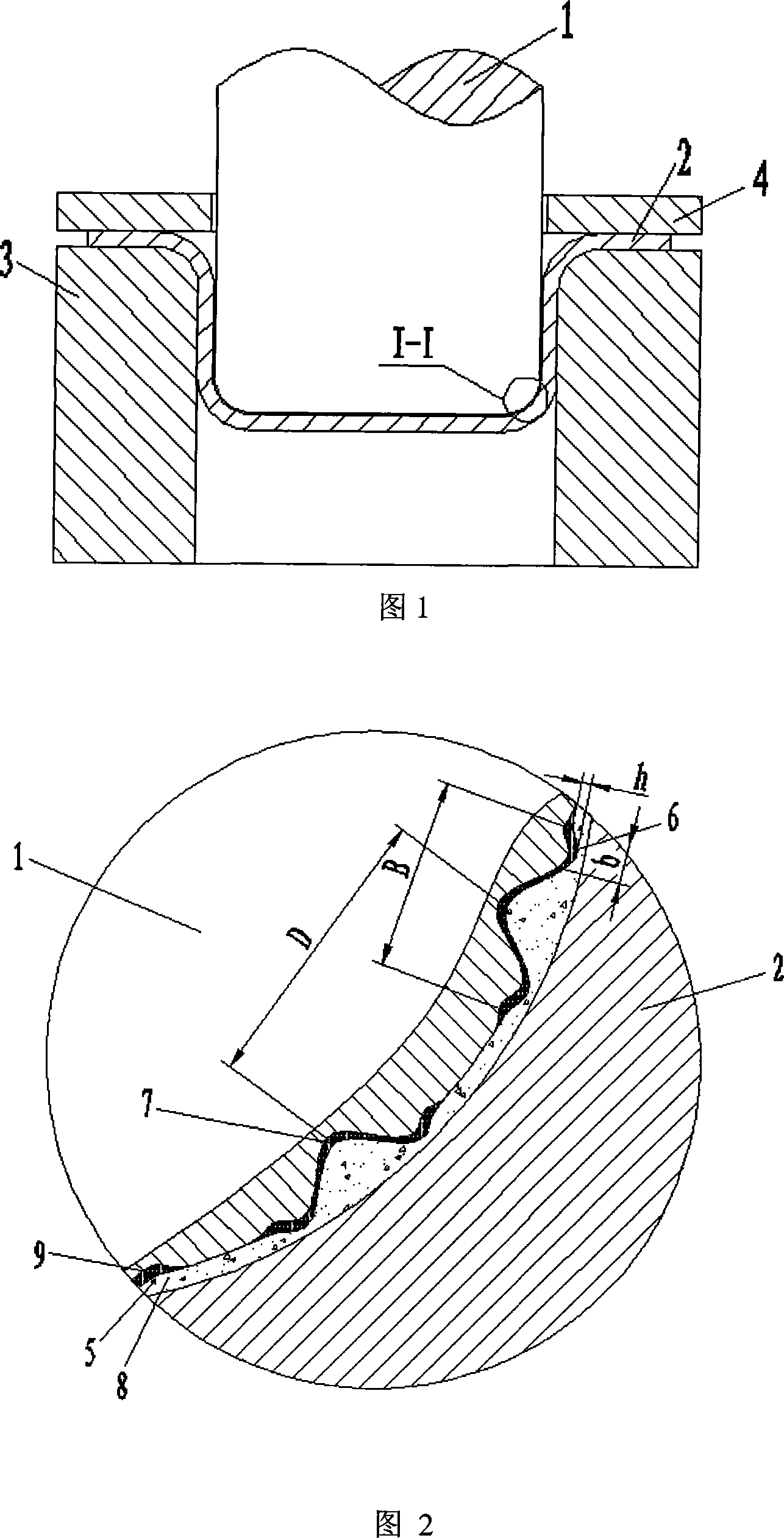
The invention is a forming mould and a manufacturing method of a laser texturing metal plastic. After being processed by the laser, the hardness of a surface of the forming mould of laser texturing metal plastic is HV800 to 10000, which has the microstructure of crater-shaped micro-geometrical structure consisting of spacing and unevenly distributed micro pits and bosses around the micro pits. Wherein, the geometric parameters of the crater-shaped micro-geometrical structure are: the pit diameter (B) of the pit is 20 to 500 Mu m; the height (h) of the boss is 1 to 8 Mu m; the width (b) of the boss is 3 to 20 Mu m; and distance D between two adjacent pits is 50 to 500 Mu m. The invention has an advantage that surface material is microscopically hardened and pinning is macroscopically strengthened when plastic forming is practiced by the mould, thereby greatly improving properties of wear resistance of the mould. In addition, the micro pits on the surface of the mould can be used fro storing lubrication oil and gathering wear particles, thereby improving lubrication state of the mould to have an effect of lubrication and friction-reducing. And the special laser texturing structure of the surface optimizes forming the technology of the metal plastic.

Description

technical field [0001] The invention relates to the field of metal plastic forming molds, in particular to a method for performing laser roughening surface micro-modeling treatment on the surface of metal plastic forming molds. Background technique [0002] During metal plastic forming, due to the elastic-plastic contact friction between the mold and the workpiece under high pressure, and often under severe working conditions such as high temperature and alternating load, the mold will be deformed, cracked, fatigue cracked, worn out, and its life is low. , where the main failure mode is wear. Wear as the main failure mode of the mold is not an inherent characteristic of the material. It is related to various factors such as working conditions, materials, surface morphology, contact mode, lubricating medium and lubrication mode, and is a dynamic process of energy consumption and material damage. ,hard to control. Therefore, reducing wear and improving the service life of mo...

Claims


Application Information

Patent Timeline
IPC IPC(8): B21D37/10B23K26/36
Inventor 符永宏张健
Owner JIANGSU UNIV
Why Eureka
Eureka Blog
Learn More