
Variable bandwidth filter circuit for RFID read-write equipment

A technology of filter circuit and reader, which is used in instruments, cooperating devices, computer parts, etc.

Inactive Publication Date: 2008-03-19
ZHEJIANG XINGSHENG IOT TECH
View PDF0 Cites 7 Cited by
  • Summary
  • Abstract
  • Description
  • Claims
  • Application Information

AI Technical Summary

Problems solved by technology

However, a simple RC high-pass circuit is difficult to meet the above two requirements at the same time

Method used


Image

  • Variable bandwidth filter circuit for RFID read-write equipment
  • Variable bandwidth filter circuit for RFID read-write equipment

Examples


Embodiment Construction

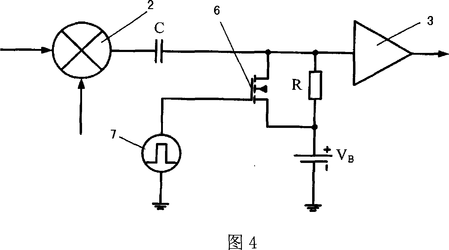
[0014] The invention provides a variable bandwidth filter circuit for an RFID reader. The circuit structure is shown in Figure 4, a high-pass filter composed of a capacitor C and a resistor R is connected between the down-conversion mixer 2 and the intermediate frequency amplifier 3; a controllable MOS transistor switch 6 is connected in parallel at both ends of the resistor R of the high-pass filter circuit , constitute a high-speed filter circuit with variable bandwidth. The control electrode of the MOS transistor is connected to the pulse control signal 7, and the source of the MOS transistor and the node of the resistor R are connected to the bias voltage VB.

[0015] A MOS transistor switch is connected in parallel at both ends of the resistor R. Since the reference square wave signal is emitted by the reader itself, coupled through the space and the substrate, and then received by the radio frequency receiver, the moment of its appearance and end is known, so it can be ...


PUM


Abstract

The present invention discloses a variable bandwidth filter circuit, which belongs to the design field of analog integrated circuits, in particular relates to a coupling filter circuit in the radio frequency receiver of a RFID reader, and the present invention can be used in RFID readers. A high-pass filter consisting of a capacitor C and a resistor R is connected between a lower-frequency-conversion mixer which converts frequency directly and an intermediate-frequency amplifier; two ends of the resistor R are connected in parallel with controllable MOS-tube switches to form a high-speed filter circuit with variable bandwidth; used in the RFID reader integrated circuits, the high-pass filter circuit can flit out DC and low frequency components led by directly converting frequency; under specific input signal, the bandwidth of the high-pass filter circuit can change with the signal by connecting in parallel controllable switches on two ends of the resistance in the filter circuit to have quickly respond, thereby improving the speed of the reader.

Description

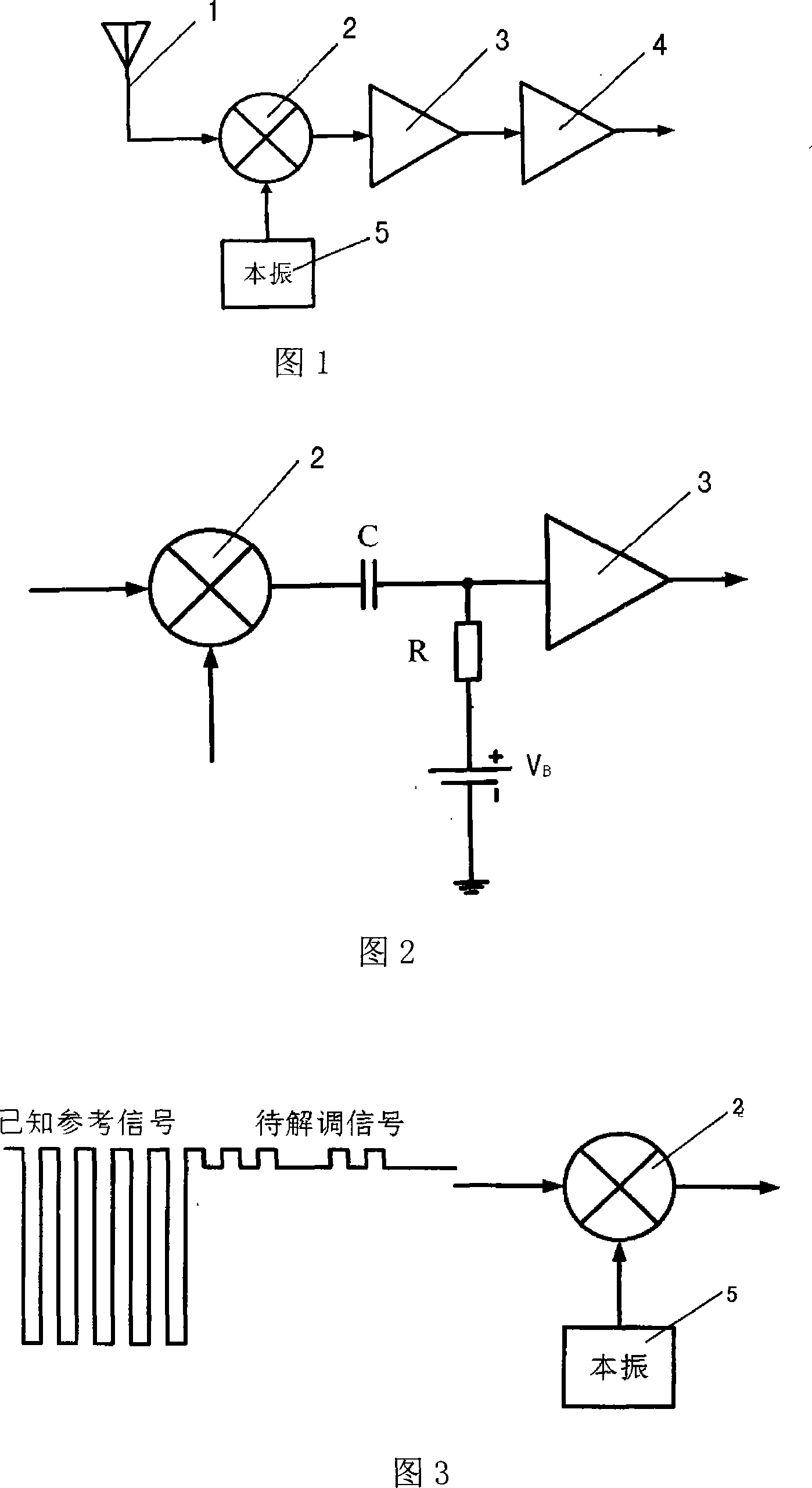
technical field [0001] The invention belongs to the field of analog integrated circuit design, in particular to a variable bandwidth filter circuit for an RFID reader-writer, which is a coupling filter circuit in a radio frequency receiver of the RFID reader-writer. Background technique [0002] Radio Frequency Identification (RFID) technology is a non-contact automatic identification technology. Its basic principle is to use radio frequency signals and their spatial coupling and transmission characteristics to realize automatic identification of stationary or moving objects. A radio frequency identification system generally includes several parts such as radio frequency tags, readers and hosts. Among them, the reader includes a radio frequency receiver, a radio frequency transmitter and a digital baseband part. The block diagram of the radio frequency receiver realized by the integrated circuit is shown in Fig. 1 . [0003] In Figure 1, the radio frequency reception is pe...

Claims


Application Information

Patent Timeline
IPC IPC(8): G06K17/00
Inventor 王自强高天宝张春王志华
Owner ZHEJIANG XINGSHENG IOT TECH
Learn More