On-site hydrogen producing method and on-site hydrogen producing device

An on-site, reforming hydrogen production technology, applied in chemical instruments and methods, hydrogen, inorganic chemistry, etc., can solve the problems of hydrogen permeation rate and hydrogen selectivity decline

Active Publication Date: 2008-03-26
BYD CO LTD
View PDF4 Cites 9 Cited by
  • Summary
  • Abstract
  • Description
  • Claims
  • Application Information

AI Technical Summary

Problems solved by technology

During the use of the fuel processor, the mixed gas generated in the reforming area directly enters the membrane module for separation. Due to the high concentration of carbon monoxide in the mixed gas (generally 3-6 volume %), the high-concentration When carbon monoxide is in contact with the selectively hydrogen-permeable membrane, it is easy to passivate the selectively hydrogen-permeable membrane, so after the fuel processor has been in operation for a period of time, the hydrogen-selectively permeable membrane in the membrane module is easily passivated. , so that the hydrogen permeation rate and hydrogen selectivity of the membrane that is selectively permeable to hydrogen are reduced

Method used


Image

  • On-site hydrogen producing method and on-site hydrogen producing device
  • On-site hydrogen producing method and on-site hydrogen producing device
  • On-site hydrogen producing method and on-site hydrogen producing device

Examples


Embodiment 1

[0047] This embodiment is used to illustrate the on-site hydrogen production method and on-site hydrogen production device provided by the present invention.

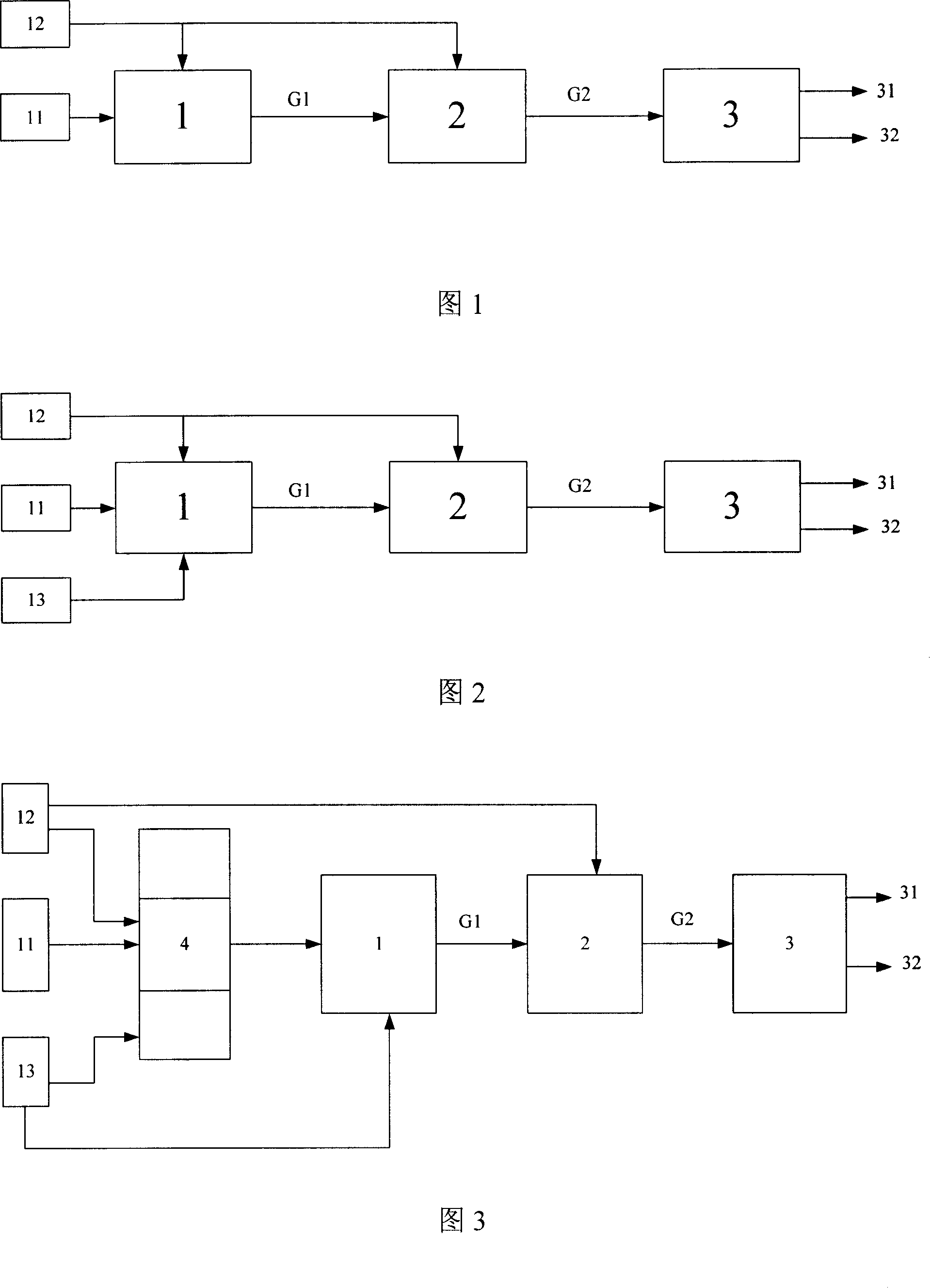
[0048] An on-site hydrogen production device as shown in Figure 3 was prepared.

[0049] Wherein, the carbon-containing raw material supply device 11 and the water supply device 12 are all rectangular parallelepiped storage tanks of 150 mm * 150 mm * 200 mm made of stainless steel.

[0050] The oxygen-containing gas supplier 13 is a gas bottle filled with compressed air; the reforming hydrogen production reactor 1 is a 1.4-liter tubular reactor made of 0.3 mm thick stainless steel 316.

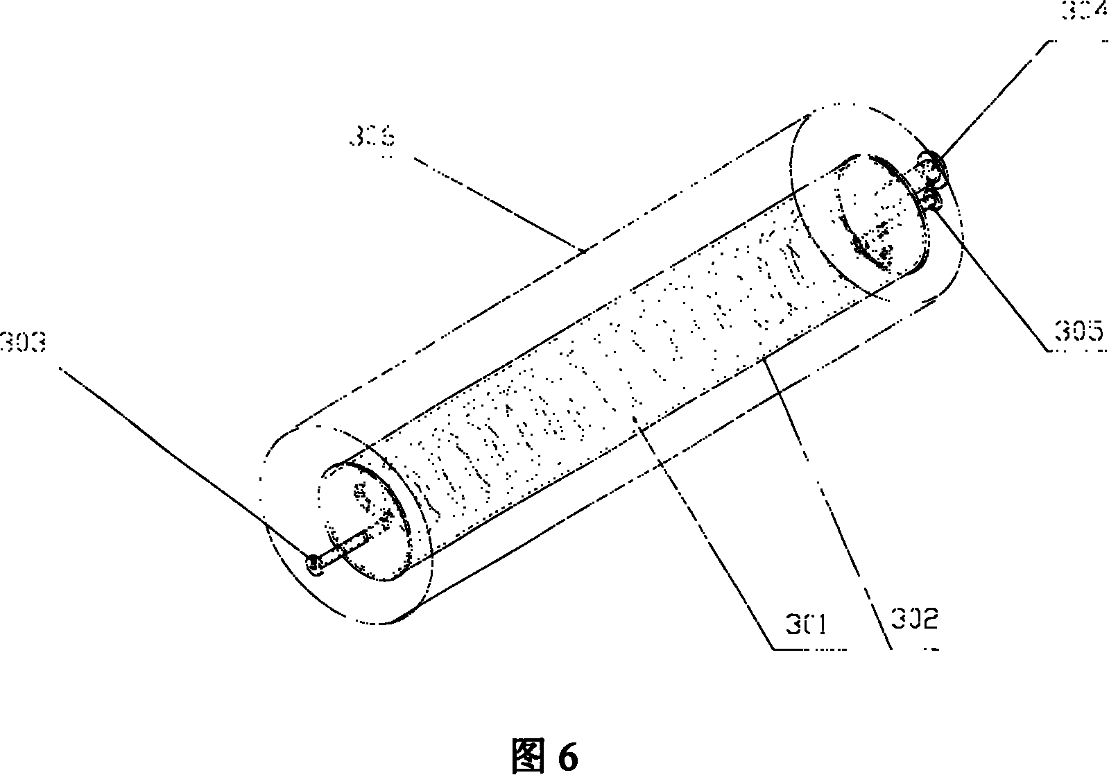
[0051] The structure of the hydrogen separator 3 is shown in Figure 6, the housing 306 and the hydrogen collection chamber 302 are tubular containers made of stainless steel 316, the length of the housing 306 is 20 centimeters, and the inner diameter is 2.6 centimeters, The hydrogen collection chamber 302 has a length of 10 cm and an i...

Embodiment 2

[0058] This embodiment is used to illustrate the on-site hydrogen production method and on-site hydrogen production device provided by the present invention.

[0059] Adopt the same device, material and connection method as in Example 1 to prepare the on-site hydrogen production device as shown in Figure 3, the difference is that the catalyst in the reforming hydrogen production reactor 1 is a Cu-Zn-La alloy (Cu, Zn The molar ratio with La is 1:0.4:0.4) (Selectra (TM) catalyst produced by Yingge Chemical Company), supported on Al 2 o 3 On the coating, the coating density is 30 g / cm2, Al 2 o 3 The coating is coated on a 400-mesh cordierite honeycomb carrier, and the coating thickness is 20 microns; the water conversion catalyst is supported on Al 2 o 3 Pd-Cu alloy on the coating (the molar ratio of Pd and Cu is 1: 0.5) (Selectra (TM) catalyst produced by Yingge Chemical Company), coating density 20 grams / square centimeter, Al 2 o 3 Coated on a 400-mesh FeCrAl alloy honeyc...

Embodiment 3

[0062] This embodiment is used to illustrate the on-site hydrogen production method and on-site hydrogen production device provided by the present invention.

[0063] Adopt the same device, material and connection method as in Example 1 to prepare the on-site hydrogen production device as shown in Figure 3, the difference is that the catalyst in the reforming hydrogen production reactor 1 is a Pd-Ce alloy (the mole of Pd and Ce The ratio is 1:0.2) (Selectra (TM) catalyst produced by Yingge Chemical Company), supported on Al 2 o 3On the coating, the coating density is 30 g / cm2, Al 2 o 3 The coating is coated on a 400-mesh cordierite honeycomb carrier, and the coating thickness is 15 microns; the water conversion catalyst is supported on Al 2 o 3 Pd-Cu-Cr alloy on the coating (the molar ratio of Pd, Cu and Cr is 1: 0.5: 0.2) (Selectra (TM) catalyst produced by Yingge Chemical Company), coating density 20 grams / square centimeter, Al 2 o 3 Coated on a 400-mesh FeCrAl alloy h...


PUM

PropertyMeasurementUnit
thicknessaaaaaaaaaa
thicknessaaaaaaaaaa
diameteraaaaaaaaaa

Abstract

The in-situ hydrogen preparing process includes contacting carbon-containing material and water inside one reforming hydrogen-making reactor in reforming hydrogen-making condition to produce hydrogen-rich gas mixture; and separating hydrogen from the gas mixture inside one hydrogen separator after contacting the hydrogen-rich gas mixture and water inside one water converting reactor in the presence of water converting catalyst containing one or several of Cu-Zn alloy, Pd-Cu alloy, Pd-Cu-Cr alloy and Pt-Ce alloy. The in-situ hydrogen preparing process has hydrogen-rich gas mixture with CO less than 2 vol% and no deactivation of the selective hydrogen penetrating film in the hydrogen separator.

Description

technical field [0001] The invention relates to a hydrogen production method and a hydrogen production device, more particularly to an on-site hydrogen production method and an on-site hydrogen production device. Background technique [0002] A fuel cell is a power generation device that directly converts chemical energy contained in chemical substances into electrical energy by using redox reactions. It is considered to be a clean energy source in the 21st century and will be widely used in automotive power sources and distributed power generation systems. . Among them, the proton exchange membrane fuel cell with hydrogen as the energy carrier is the most widely used. It uses high-purity hydrogen as fuel and oxygen as an oxygen-containing gas. The two react at the anode and cathode respectively to generate electricity. The reaction product is only water. Features of high efficiency and environmental protection. Although proton exchange membrane fuel has the above advantag...

Claims


Application Information

Patent Timeline
Patent Type & Authority Applications(China)
IPC IPC(8): C01B3/32
Inventor 周良董俊卿
Owner BYD CO LTD
Why Eureka
Try Eureka