
Device for high-throughout monitoring micro-array biomolecule reaction by light reflection difference method

A biomolecular, high-throughput technology, applied in the field of microarray biomolecular reaction monitoring devices, to achieve the effect of improving signal-to-noise ratio, high work efficiency, and easy operation

Inactive Publication Date: 2008-04-02
INST OF PHYSICS - CHINESE ACAD OF SCI
View PDF0 Cites 18 Cited by
  • Summary
  • Abstract
  • Description
  • Claims
  • Application Information

AI Technical Summary

Problems solved by technology

[0004] The purpose of the present invention is to overcome the defects of the existing OIRD biomolecular monitoring technology, thereby providing a device that does not need to move samples, has short monitoring time, and low system noise, and can monitor microarray biomolecular reactions with high throughput using the light reflection difference method

Method used


Image

  • Device for high-throughout monitoring micro-array biomolecule reaction by light reflection difference method

Examples


Embodiment 1

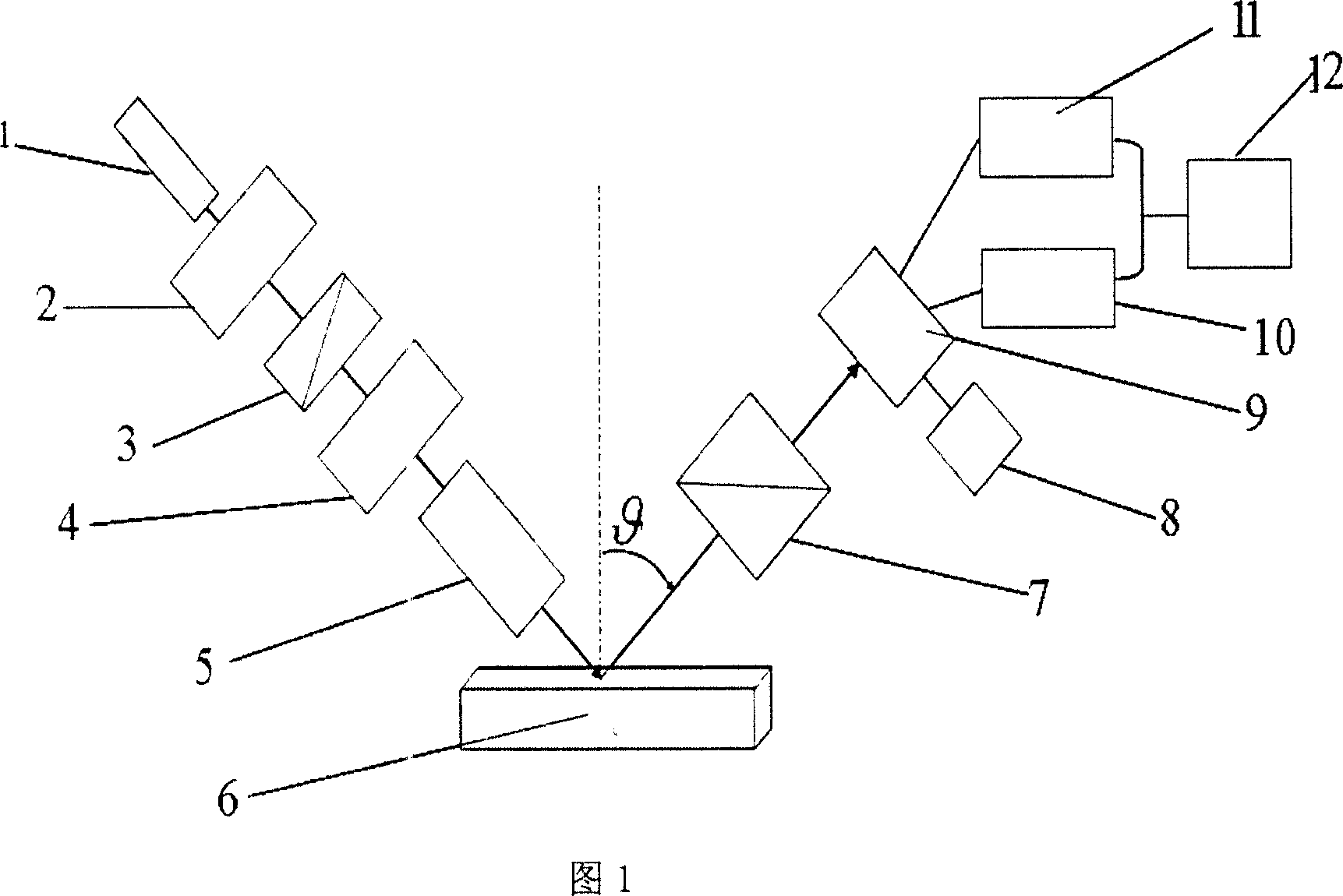
[0033] Referring to Figure 1, a device for high-throughput monitoring of microarray biomolecule reactions is made by the light reflection difference method.

[0034] The device is composed of an incident light path, a sample stage 6, an output light path, and a data acquisition and processing system. The incident light path includes a polarizer 2, a photoelastic modulator 3, and a phase shifter 4 on the optical path in front of the laser 1 output light. And the beam expander 5; the exit light is routed to the analyzer 7 and the photoelectric signal converter 9. The incident light beam emitted from the incident light path is reflected by the sample on the sample stage 6 and then sequentially passes through the analyzer 7 and the photoelectric signal The signal converter is electrically connected to the data acquisition and processing system 12. The photoelectric signal converter is composed of a silicon photodiode array 9, a switch circuit, a first lock-in amplifier 10, and a secon...

Embodiment 2

[0041] In this embodiment, the phase shifter 4 adopts a Puck box with a model of Cleveland Crystal IMPACT10. Others are the same as Embodiment 1. The sensitivity of the device in this embodiment can be improved by an order of magnitude compared with Embodiment 1.

Embodiment 3

[0043] In this embodiment, the switch circuit 8 is used instead of the relay switch circuit. Others are the same as the embodiment 1. The time for the device to monitor the same biochip sample can be shortened by 0.5 minutes compared with the embodiment 1.


PUM

PropertyMeasurementUnit
Wavelengthaaaaaaaaaa
Diameteraaaaaaaaaa

Abstract

The invention provides a device for high-flux monitoring of micro array biomolecular reaction through light reflex difference method, comprising an incident light path, a sample table, an emergent light path and a data acquisition and processing system, wherein, the incident light path comprises a laser, a polarizer, a photoelastic modulator, a phase shifter and a beam expander arranged between the phase shifter and the sample table; the emergent light path comprises a polarization analyzer and an electrooptical signal converter; the electrooptical signal converter comprises a silicon photodiode array, a pulse switching circuit, a first phase-locked amplifier and a second phase-locked amplifier; the output end of the silicon photodiode array is respectively in electric connection with the input ends of the pulse switching circuit, the first phase-locked amplifier and the second phase-locked amplifier. With a simple structure and easy operation, the device reduces the noise caused by moving a sample and greatly improves signal-noise ratio; meanwhile, the device can complete non-mark quick high-flux monitoring of the reactions of the array elements of a micro array at the same time, thereby greatly increasing monitoring efficiency.

Description

Technical field [0001] The invention relates to a microarray biomolecular reaction monitoring device, in particular to a high-throughput, fast and label-free monitoring device for biomolecular reactions. Background technique [0002] The commonly used methods for monitoring biomolecules are fluorescent labeling and surface plasmon resonance. Fluorescent labeling is a commonly used destructive monitoring method. This method has the disadvantages of complex monitoring process, can change the structure of protein molecules and produce photobleaching phenomenon; surface plasmon resonance is currently commonly used label-free monitoring of biomolecular interactions Method, this method requires the biomolecule microarray to be constructed on the functional gold film, and the thickness and uniformity of the gold film are very high. [0003] Oblique-incidence reflectivity difference (OIRD) is a high-sensitivity and special optical measurement technology for measuring the optical properti...

Claims


Application Information

Patent Timeline
IPC IPC(8): G01N33/50G01N21/00
Inventor 张洪艳王旭吕惠宾陆珩曹玲柱宁廷银孙志辉周岳亮金奎娟杨国桢
Owner INST OF PHYSICS - CHINESE ACAD OF SCI
Learn More