Polarization light splitter and LCOS LCD stereo projection system using the same

A polarization beam splitter and polarization splitting technology, applied in stereoscopic systems, optics, instruments, etc., can solve the problems of impossible availability of S polarized light, difficulty in assembly adjustment, high cost, etc., to eliminate residual reflection at the interface and reduce interface Effects of residual reflections, high isolation and contrast

Active Publication Date: 2008-04-16
BUTTERFLY TECH SHENZHEN
View PDF6 Cites 14 Cited by
  • Summary
  • Abstract
  • Description
  • Claims
  • Application Information

AI Technical Summary

Problems solved by technology

The liquid crystal display system of this structure needs to use three liquid crystal panels, and other multiple optical devices, and the cost is expensive
[0006] The patent CN03803103.5 of French Thomson Charter Company in China discloses a kind of stereoscopic light engine architecture, as shown in Figure 1, this projection system has only used two liquid crystal micro-display devices (LCOS), but has used four simultaneously. A polarizing beam splitter appears to have a complex and cumbersome structure, and it is difficult to assemble and adjust, and the invention also uses a number of optical filters, which will waste a part of the light and affect the light intensity, and the cost of the invention has not been reduced.
In Chinese patent CN03137759.9 (the name is a kind of LCOS liquid crystal stereoscopic projection optical machine) also announced similar projection display structure, this patent also used two LCOS liquid crystal panels, and the light-splitting surface of four polarization beam splitters constitutes "meter" In this structure, multiple white light wave plates are used to convert the polarization of light. The structure of this invention is also complicated, and the wide-band wave plate leads to low light efficiency.
[0007] Another Chinese patent CN200380104730.6 of the French Thomson Charter Company discloses a high-contrast stereoscopic projection system, which has a first channel (containing two LCOS liquid crystal panels and a polarizing beam splitter), a second channel (containing two LCOS liquid crystal panels , a polarization beam splitter), a relay lens system is provided between the first channel and the second channel to realize light transmission, and the second channel is used to perform secondary modulation on the S-polarized light and P-polarized light emitted by the first channel, again S-polarized light and P-polarized light are formed and projected to the projection lens system to display stereoscopic images. This patent can indeed provide high-contrast image quality, but the structure seems to be more complicated and the cost is higher
[0008] Aiming at the above-mentioned three-dimensional projection system with a relatively complicated structure, U.S. Patent US7059728 and Chinese Patent CN03141689.6 both propose a three-dimensional projection display device using only one polarization beam splitter and two LCOS (liquid crystal on silicon) panels. A polarizing beam splitting surface, as shown in Figure 2, this structure has been presented in FIG6 of US0759728 and in the abstract drawing of CN03141689.6, although this structure is simple and compact, it is actually not useful for stereoscopic display, The polarization beam splitter and other optical devices in this structure can make the purity of P-polarized light higher, but it is impossible to achieve the purity of S-polarized light to a practical level, because the current coating technology cannot meet this requirement. Require
The contrast and isolation of the P-polarized light and S-polarized light produced by the projection system are very low, and the image display quality is not good, and it is difficult for the audience to really feel the stereoscopic display effect.
[0009] It is known from the above that the stereoscopic display projection systems that appear at this stage are either complicated in structure and expensive, or have a slightly simpler structure but cannot really achieve a good stereoscopic display effect. In order to meet the needs of stereoscopic display, the projection system has to be configured. more optics

Method used


Image

  • Polarization light splitter and LCOS LCD stereo projection system using the same
  • Polarization light splitter and LCOS LCD stereo projection system using the same
  • Polarization light splitter and LCOS LCD stereo projection system using the same

Examples


Embodiment 1

[0065] Please refer to Figure 5, the LCOS liquid crystal stereoscopic projection system includes: a light source assembly (not shown) that outputs an unpolarized light beam 1, a polarizer that converts the unpolarized light beam 1 into polarized light and divides it into P polarized light and S polarized light The beam splitter 2 is two LCOS liquid crystal panels 3 and 4 synchronously driven by the image signal, wherein the P polarized light and the S polarized light emitted from the polarization beam splitter 2 are respectively projected to the above two LCOS liquid crystal panels 3 and 4 After being modulated and reflected, a beam of light is synthesized by the polarization beam splitter 2 and enters the projection lens 12 .

[0066] The light source assembly generally includes a light source, a shaping and homogenizing lens system, and a focusing lens. The light source can be a high-pressure mercury lamp or an LED, or other suitable light source to generate light suitable fo...

Embodiment 2

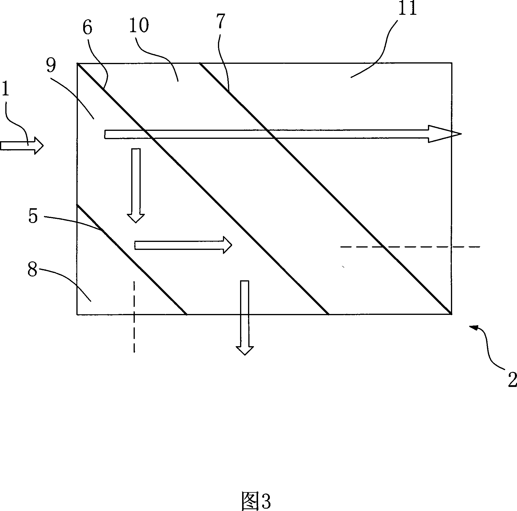
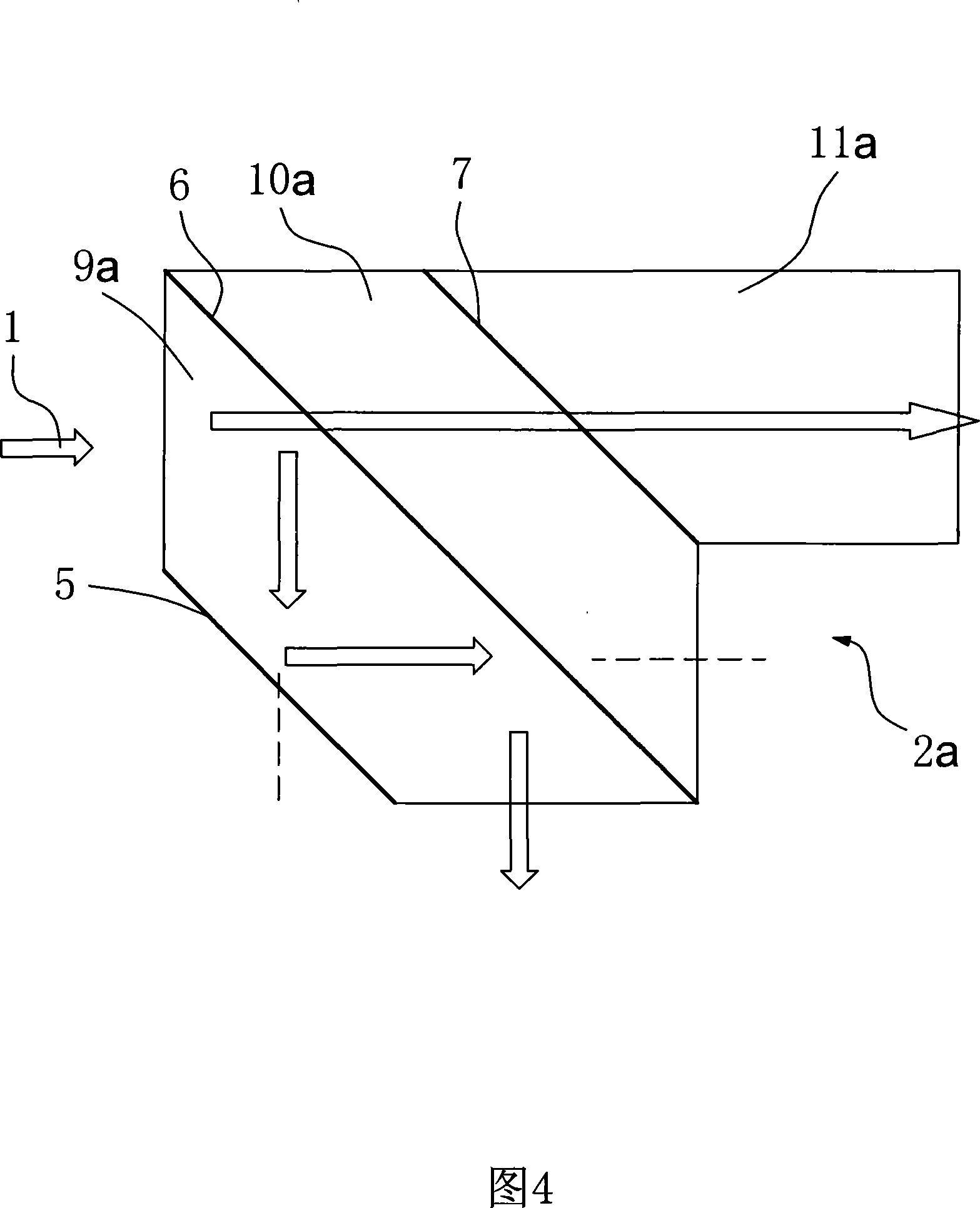
[0075] Referring to FIG. 6, the stereoscopic display liquid crystal projection system of the present invention adopts the polarizing beam splitter 2a with the structure shown in FIG. The polarization beam splitter 2 a includes three polarization beam splitting planes: a second polarization beam splitting plane 5 , a first polarization beam splitting plane 6 and a third polarization beam splitting plane 7 , the specific structure of which has been described above.

[0076] The light source assembly (not shown in the figure) provides ±8° rectangular collimated white light 1 to enter the polarization beam splitter 2a, and the incident light beam 1 splits S-polarized light and P-polarized light on the first polarized beam-splitting surface 6, and then S polarized light After the polarized light enters the second polarization splitting surface 5, it is reflected to the first polarization splitting surface 6, and then it is reflected again by the first polarization splitting surface ...


PUM


Abstract

The invention relates to a polarization light splitter and an LCOS liquid crystal stereographic projection system which uses the polarization light splitter. The polarization light splitter mainly comprises a non-light tight prism and polarization light splitting faces arranged on the prism, wherein, the polarization light splitter comprises three polarization light splitting faces and is combined into a whole by three or four prisms; thereby the polarization light splitter has the advantages of simple structure and good light utilization factor; moreover, unpolarized lights which pass through the polarization light splitter can be split into an S polarized light and a P polarized light which are relative high in purity. The LCOS liquid crystal stereographic projection of the invention adopts the polarization light splitter and two LCOS liquid crystal panels synchronously driven by image signals; before the S polarized light and the P polarized light are finally projected onto the projecting lens, the S polarized light and the P polarized light undergo three filtrations and two filtrations respectively, which contributes to the relatively high contrast; moreover, the separation between the S polarized light and the P polarized light which carry different image signals respectively is quite high. The projection system of the invention has the advantages of compact structure, and good image quality and stereo display effect.

Description

technical field [0001] The invention relates to the field of polarization beam splitter and projection display technology, in particular to a polarization beam splitter and a stereoscopic display LCOS liquid crystal projection system using the polarization beam splitter. Background technique [0002] People's pursuit of image display quality has changed from the past two-dimensional plane image to three-dimensional display image. The purpose of people's pursuit is to watch high-contrast, high-definition and real images. The reason why human beings can see three-dimensional images is that our eyes can see things independently, and the viewing angles of the images observed by the two eyes are different, resulting in image differences in the two eyes, which stimulate the visual nerves of the brain to produce the feeling of three-dimensional viewing. Based on this, humans have extensively carried out research on stereoscopic display technology. Currently, there are four mainstre...

Claims


Application Information

Patent Timeline
Patent Type & Authority Applications(China)
IPC IPC(8): G02B27/28G02B27/10H04N13/00
Inventor 王仁贵左国梁何兵何建平和建航张权
Owner BUTTERFLY TECH SHENZHEN
Why Eureka
Try Eureka