Data driver and display device

A data driver and differential pair technology, which is applied in the field of data drivers and display devices, can solve the problems of large noise in the output signal and inability to stabilize the output signal, and achieve the effects of reducing area, saving area, and low power consumption

Inactive Publication Date: 2008-05-14
RENESAS ELECTRONICS CORP
View PDF4 Cites 8 Cited by
  • Summary
  • Abstract
  • Description
  • Claims
  • Application Information

AI Technical Summary

Problems solved by technology

However, when amplifying and outputting voltage signals of different levels corresponding to image data according to each output period, there is the following problem: when the operational amplifier in FIG. The potential fluctuation of the terminal due to capacitance, etc., will generate large noise in the output signal
Especially when the state is switched in a short time, there is a problem that the output signal cannot be stabilized within a predetermined period (period T1 or T2 in FIG. 12(B)).

Method used


Image

  • Data driver and display device
  • Data driver and display device
  • Data driver and display device

Examples


Embodiment Construction

[0117] The above-mentioned present invention will be further described in detail below with reference to the accompanying drawings.

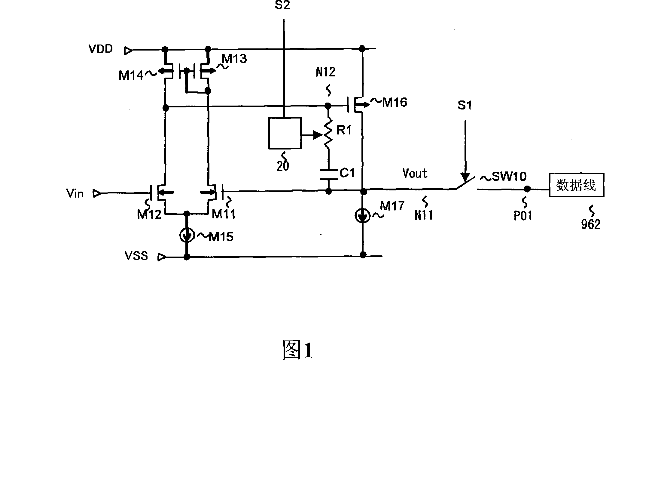
[0118] FIG. 1 is a diagram showing the structure of a first embodiment of the present invention. FIG. 1 is a diagram showing the structure of an output buffer of a data driver of a liquid crystal display device.

[0119] In this embodiment, in an amplifier circuit (see FIG. 12(A)) having a phase compensation capacitor C1 and a zero point compensation resistor R1 connected in series with the phase compensation capacitor C1, a device for controlling the resistance value of the zero point compensation resistor R1 is provided. control circuit 20.

[0120] The amplifier circuit according to this embodiment includes: a current source M15 whose first terminal is connected to the low-order side power supply VSS; and a differential pair composed of N-channel transistors M11 and M12 whose common source is connected to the second terminal of the current s...


PUM


Abstract

Disclosed is a data driver including a zero compensation resistor connected in series with a phase compensation capacitor between an output node of an input differential amplification stage and an output node of a succeeding amplification stage, and a control circuit that controls to switch a resistance value of the zero compensation resistor. The control circuit switches the resistance value of the zero compensation resistor to a first resistance value or a second resistance value larger than the first resistance value in response to turning off or on of an output switch that controls connection between the output terminal of an amplifying circuit and a data line.

Description

technical field [0001] The invention relates to a data driver and a display device using the data driver. Background technique [0002] Recently, in addition to mobile phones (mobile-phones, cellular-phones), notebook computers, and monitors, the demand for large-screen liquid crystal televisions has also expanded. These liquid crystal display devices use active matrix drive type liquid crystal display devices that can perform high-definition display. First, a typical structure of an active matrix driving type liquid crystal display device will be described with reference to FIG. 11 . In addition, in FIG. 11, the main structure connected to one pixel of a liquid crystal display part is schematically shown by an equivalent circuit. [0003] Generally, the display unit 960 of an active matrix liquid crystal display device is formed by facing two substrates, a semiconductor substrate and an opposite substrate, and sealing liquid crystal therebetween. In pixel columns×1024 pi...

Claims


Application Information

Patent Timeline
Patent Type & Authority Applications(China)
IPC IPC(8): G09G3/36H03F3/45
CPCG09G2310/027G09G3/3688
Inventor 土弘
Owner RENESAS ELECTRONICS CORP
Why Eureka
Try Eureka