Pumping unit with pole

A technology for oil pumping and oil pumping mechanism, which is applied in the directions of transmission, production fluid, wellbore/well components, etc., can solve the problems of long operation time, energy waste, large volume and weight and manufacturing cost, and achieve the improvement of useful work power. , the effect of reducing the load

Inactive Publication Date: 2008-05-21
CHONGQING UNIVERSITY OF SCIENCE AND TECHNOLOGY +1
View PDF0 Cites 10 Cited by
  • Summary
  • Abstract
  • Description
  • Claims
  • Application Information

AI Technical Summary

Problems solved by technology

[0003] In actual production and use, the disadvantages of the beam pumping unit with rods are: 1. The volume and weight are large, and the longer the stroke, the more prominent this problem is, so that it is difficult to further increase its stroke; with the gradual increase of the oil well depth , especially the number of heavy oil and high waxy oil wells is increasing. In order to ensure the crude oil production, the pumping unit stroke is required to be as long as possible from the technical point of view.
At present, the ultra-long stroke of the stroke beam pumping unit based on the four-bar linkage mechanism in my country can reach more than 6 meters. Its volume, weight and manufacturing cost are already quite large, and it is already very difficult to increase the stroke length.
However, this stroke is far from enough for deep wells, ultra-deep wells, heavy oil wells, and high-wax oil wells, and it is difficult to meet the needs of oilfield production.
2. The motor load is uneven during the up and down strokes, that is, the load on the motor is high when moving upward, and the load on the motor is relatively low when moving downward, or even a negative load, resulting in a waste of energy
For this reason, people have adopted a variety of balance methods, such as beam balance, crank balance, compound balance, air pressure balance, etc., which have improved the load distribution of the pumping unit to varying degrees, but because they have not changed the beam in essence Because of the four-bar linkage mechanism of the pumping unit, it is impossible to fundamentally solve the problem of uneven power distribution of the pumping unit
3. Rigid sucker rods connected by threads are used to transmit ground power to the downhole. Therefore, it is very difficult to install and take out the downhole pumping equipment for maintenance. The operation time is long and the cost is high. prone to trip accidents
4. The stroke and number of strokes of the beam pumping unit can only be adjusted step by step, and cannot adapt to changes in oil well process parameters in time, which greatly limits its application range

Method used


Image

  • Pumping unit with pole
  • Pumping unit with pole
  • Pumping unit with pole

Examples


Embodiment 1

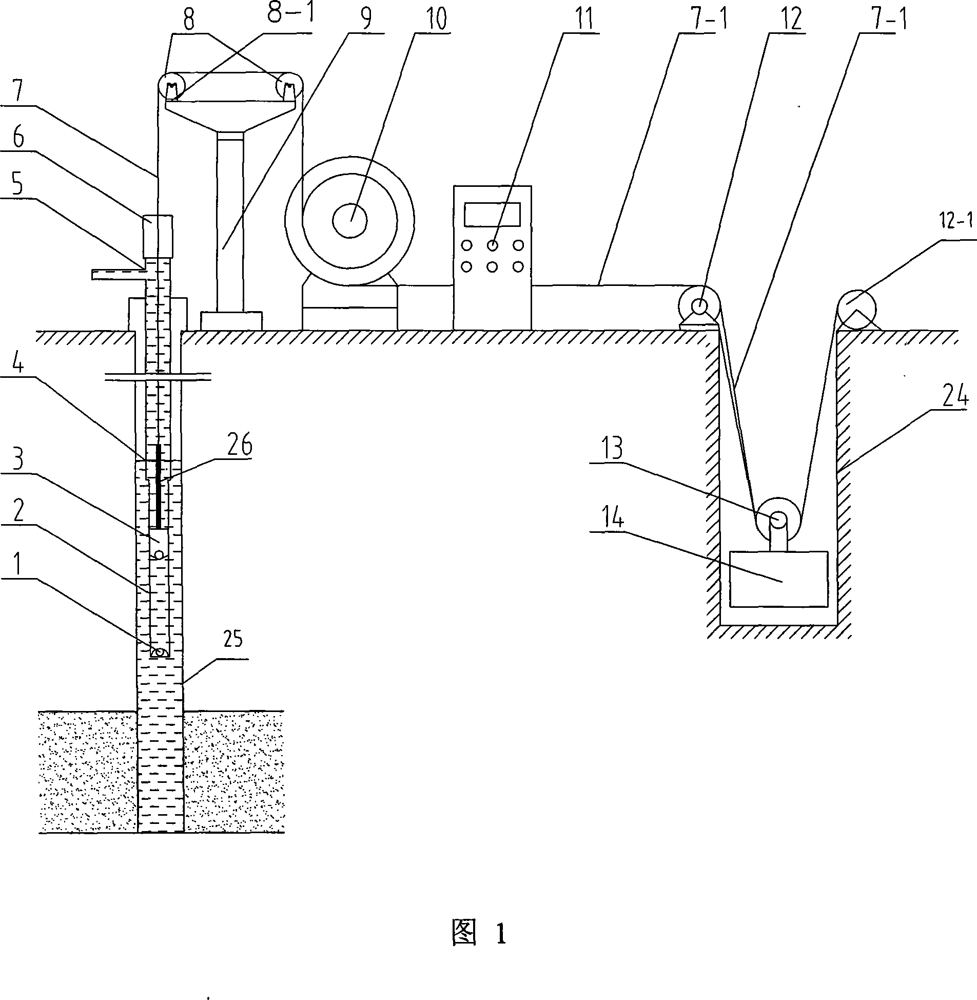
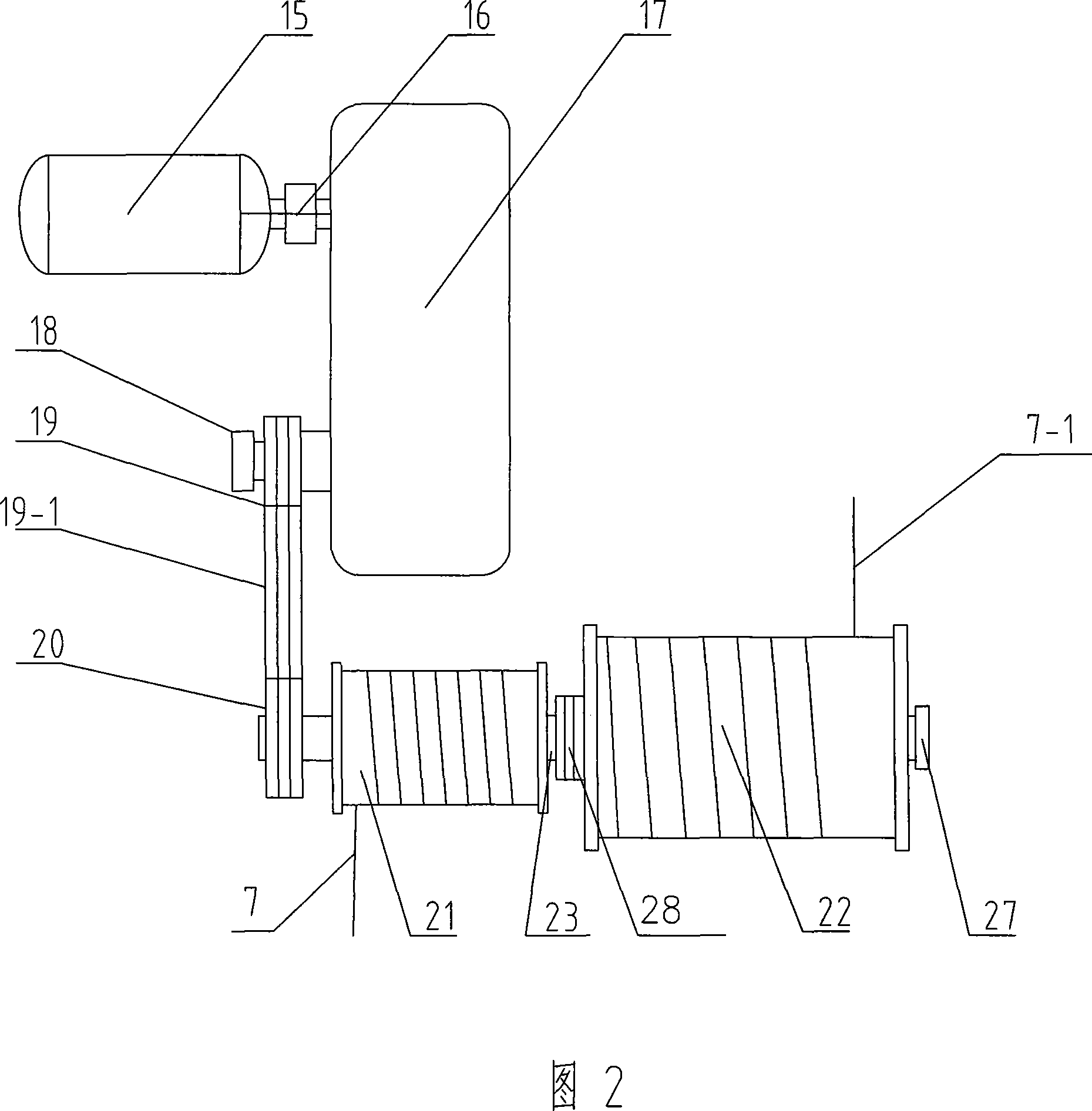
[0020] Embodiment 1: Referring to Figures 1 to 4, a rod pumping device includes a reducer 17 connected to a motor 15 via a coupling 16, an in-well pumping mechanism, and an electric control cabinet 11, characterized in that: Between the speed reducer 17 and the well pumping mechanism, a drum lifting mechanism connecting the two is added.

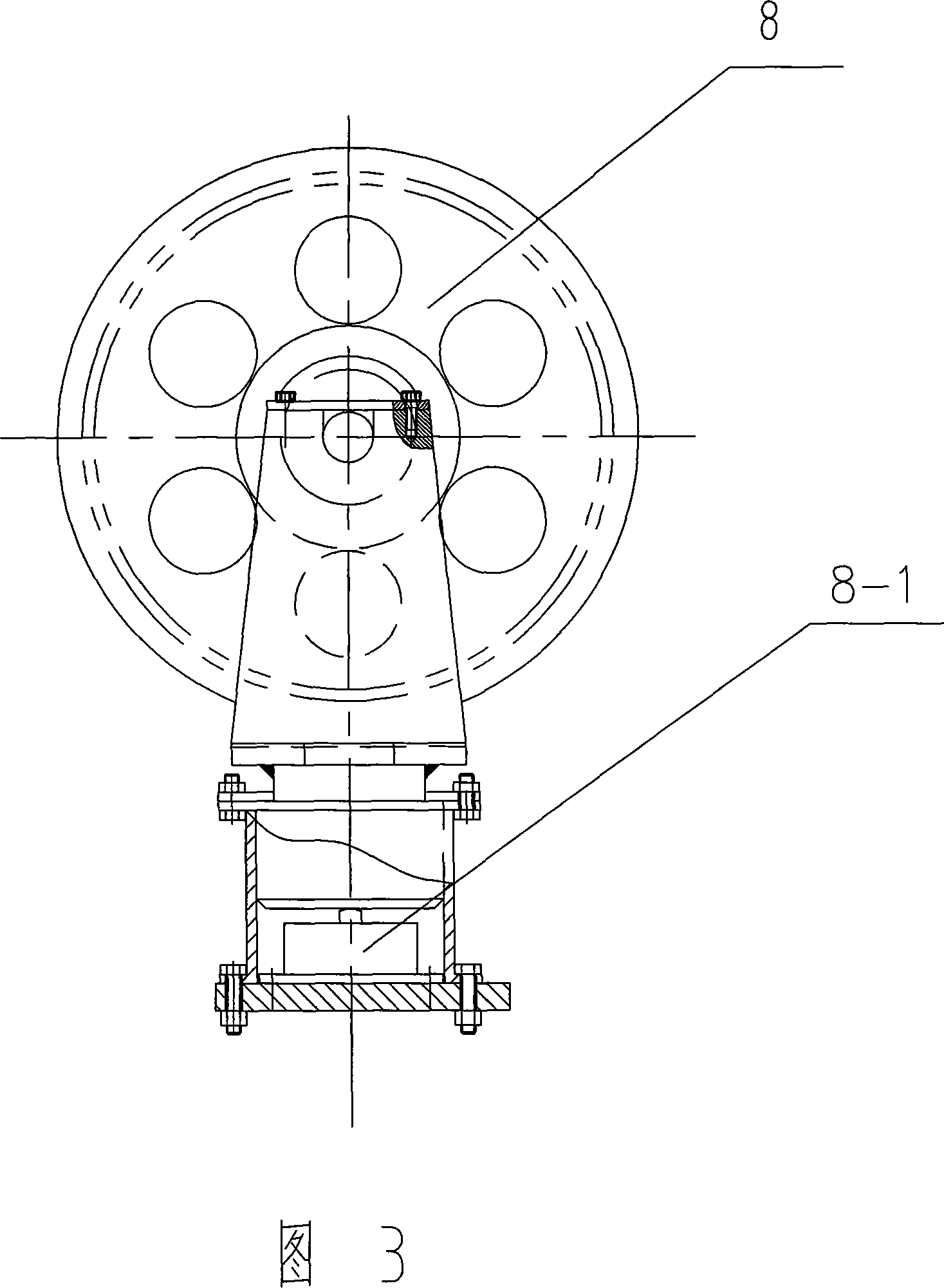
[0021]The drum lifting mechanism includes a double-drum winch 10, a steel wire rope 7 at the pumping end, a steel wire rope 7-1 at the counterweight end, a pulley support 9, a wellhead pulley 8, a redirection pulley 12, a counterweight movable pulley 13, and a movable pulley (13-1) , counterweight 14 and counterweight shaft 24; wherein, one end of the oil pumping end steel wire rope 7 is connected to the production drum 21 fixedly connected to one side on the drum shaft 23 of the double drum winch 10, and the counterweight end steel wire rope One end of 7-1 is connected to the counterweight drum 22 connected by the clutch 28 on the drum shaf...

Embodiment 2

[0024] Embodiment 2: Referring to Fig. 5, a rod oil pumping device, this embodiment is the same as Embodiment 1 except for the following structures:

[0025] 1. A counterweight support frame 29 is not provided with a counterweight well, and the counterweight support frame 29 is located above the ground, and the fixed pulleys of the counterweight support frame are fixedly connected by bolts on both sides of the top of the counterweight support frame (29) 29-1, the counterweight 14 is located on one side of the counterweight support frame 29, and the redirection pulley 12 is fixed on the ground near the other side of the counterweight support frame (29); the counterweight end The other end of steel wire rope 7-1 walks around described reversing pulley 12 and described counterweight supporting frame fixed pulley 29-1, and its end is connected with the top of described counterweight 14.

[0026] 2. The diameter of the production drum 21 is the same as that of the counterweight dru...


PUM


Abstract

The present invention relates to an oil pumping device with a pumping rod, including a motor (15), a reducer (17) connected with the motor, an underground oil pumping mechanism and an electric control cabinet (11). The present invention is characterized in that a roller lifting mechanism is added and connected between the reducer (17) and the underground oil pumping mechanism; the roller lifting mechanism includes a double-roller winch (10), an oil-pumping end steel rope (7), a counterweight end steel rope (7-1), a pulley bracket (9), a well mouth pulley (8), a bend pulley (12), a counterweight movable pulley (13), a counterweight (14) and a counterweight well (24). The oil pumping device with a pumping rod provided by the present invention, particularly suitable for a deep oil well, a dense oil well and a high wax content oil well, has the advantages of simple and reasonable structure, long stroke distance, convenient regulation, reliable operation and long service life, thus greatly decreasing the production cost and the material consumption and increasing the yield of crude oil when reducing the energy consumption.

Description

technical field [0001] The invention relates to a rod pumping device, in particular to a rod pumping device suitable for oil production in deep oil wells, heavy oil wells and high wax oil wells. Background technique [0002] There are more than 70,000 crude oil production wells in my country. Since most of the main oil fields have entered the late stage of production and the pressure of formation oil has decreased, most of the oil wells are mainly produced by mechanical oil recovery. In the mechanical oil recovery, the oil recovery of the rod pumping unit is the main one, and according to statistics, it reaches more than 90% in my country. At present, the vast majority of the major oil fields in my country are beam pumping devices with rods. The pumping device mainly includes the mechanical lifting mechanism on the ground and the pumping mechanism in the oil well. The mechanical lifting mechanism on the ground includes: motor , reducer, four-bar linkage, beam, donkey head, f...

Claims


Application Information

Patent Timeline
Patent Type & Authority Applications(China)
IPC IPC(8): E21B43/00F16H37/12
Inventor 黄新武任连城周秋沙魏昌祥
Owner CHONGQING UNIVERSITY OF SCIENCE AND TECHNOLOGY
Why Eureka
Try Eureka