
Method and apparatus for biomass ebullition, gasification and combustion

A technology of combustion device and combustion method, which is applied in the direction of combustion method, fluidized bed combustion equipment, fuel burned in a molten state, etc., and can solve the problems of no biomass gasification combustion device, increased use cost of combustion furnace, inconvenient use, etc. , to achieve the effect of high temperature, high temperature and stable operation

Inactive Publication Date: 2008-06-11
ENERGY RES INST CO LTD HENAN ACADEMY OF SCI
View PDF0 Cites 27 Cited by
  • Summary
  • Abstract
  • Description
  • Claims
  • Application Information

AI Technical Summary

Problems solved by technology

Although this combustion furnace adopts the secondary combustion method of biomass gasification and combustion, it can only use biomass briquettes, which will increase the cost of the combustion furnace, and the fuel will be burned in a stacked manner on the furnace bridge. During the combustion process, part of the unburned fuel and the formed biomass carbon will fall into the bottom of the furnace bridge and be discharged together with the ashes, causing a certain amount of waste and pollution; manual intermittent feeding and ash removal increase the amount of labor in use , is inconvenient to use, and provides an unstable flame
This kind of biomass combustion furnace that burns in a stacking manner is only suitable for small-scale civil furnaces, and there is no biomass gasification combustion device suitable for industrial applications.

Method used


Image

  • Method and apparatus for biomass ebullition, gasification and combustion
  • Method and apparatus for biomass ebullition, gasification and combustion

Examples


Embodiment Construction

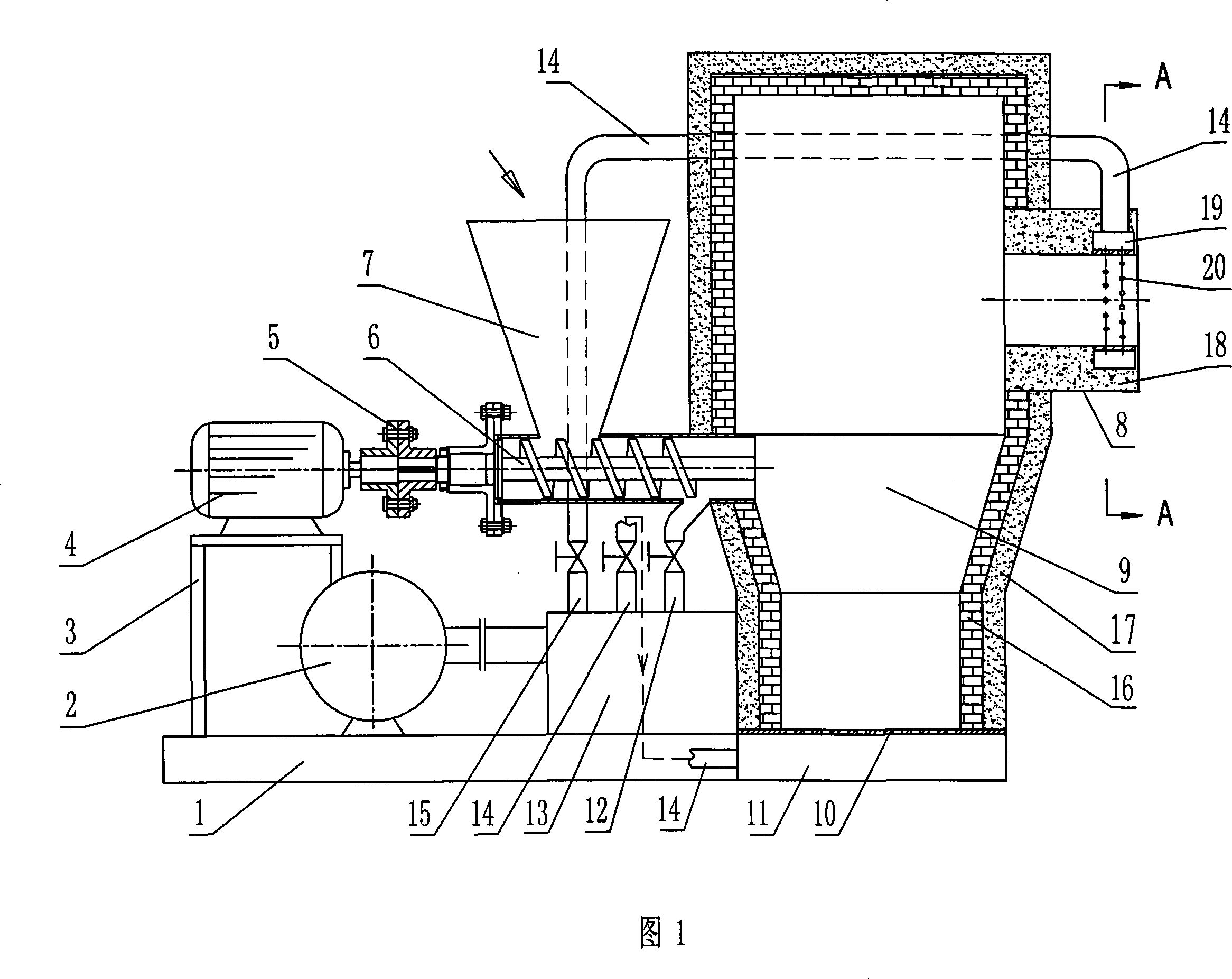
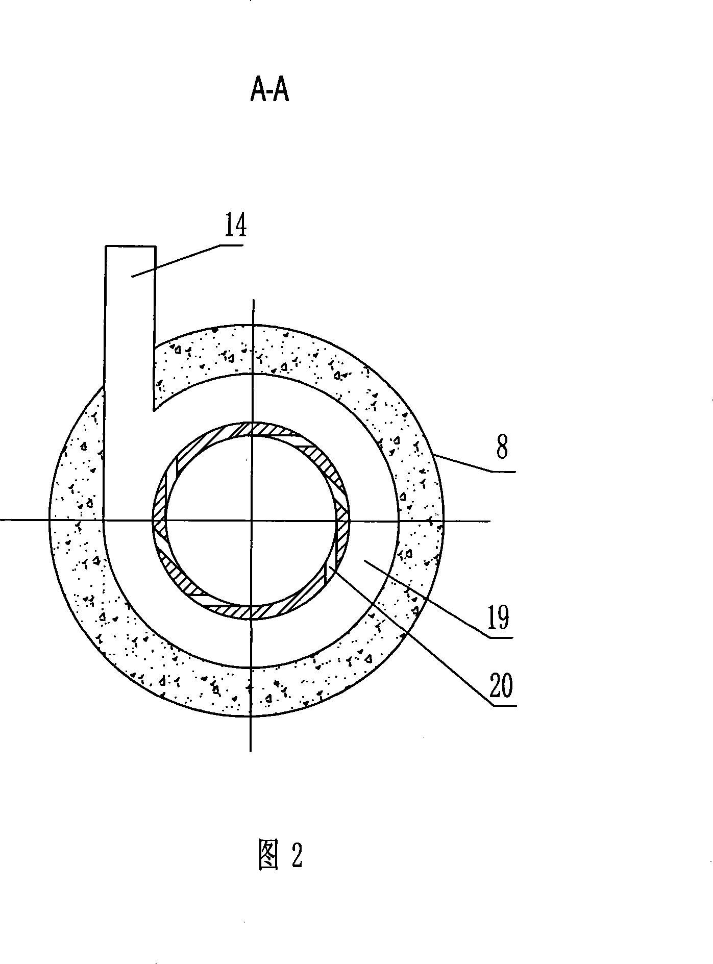
[0024] Figures 1 and 2 show biomass boiling gasification combustion devices, including a base 1, a feeding mechanism, an air supply mechanism, and a gasification combustion chamber 9 for biomass boiling gasification, and the chamber of the gasification combustion chamber 9 The wall is mainly composed of high alumina refractory brick inner lining 16 and aluminum silicate fiber outer lining 17 . The side of the base 1 is fixed with an equal pressure box 11, the top of the equal pressure box is an air distribution plate 10 with a tuyere, the gasification combustion chamber 9 is arranged on the air distribution plate 10, and the equal pressure box 11 passes through the The tuyere on the wind plate communicates with the gasification combustion chamber 9. A gas burner 8 for high-temperature gas discharge and combustion is provided on the middle and upper part of the side wall of the gasification combustion chamber 9, and an annular air duct 19 is provided at the outlet of the exhaus...


PUM


Abstract

The invention relates to a biomass boiling gasification burning method and device, which is characterized in that: blow the biomass fuel from a material inlet of a gasification firebox to the gasification firebox; the biomass fuel boils under the action of a primary flow raising from the bottom of the gasification firebox; then the biomass fuel burns incompletely under boiling status after lighted up to generate with high temperature combustible gas which can be discharged by a gas burner for direct burning. The boiling gasification burning device comprises a feeding mechanism, an air supply mechanism and the gasification firebox; a gas burner for discharging high temperature fuel gas is arranged at middle upper section of the side wall of the gasification firebox; a discharging opening of the feeding mechanism is positioned on the side wall of the gasification firebox lower than the gas burned and is communicated with the gasification firebox; a wind arrangement device is arranged at bottom of the gasification firebox; the air supply mechanism provides the gasification firebox with the primary flow through the wind arrangement device, which is communicated with the discharging opening of the feeding mechanism through the a feeding air pipe.

Description

technical field [0001] The invention relates to the technical field of biomass energy utilization, in particular to a boiling gasification combustion method and device thereof for biomass fuels such as crop stalks, sawdust and leaves, and biomass particle fuels processed from biomass fuels. Background technique [0002] Compared with conventional energy sources, biomass has the characteristics of high volatile content, low energy density, easy slagging during combustion, and corrosion to metal equipment. When biomass is directly burned in existing energy-consuming equipment, due to the large difference between the design fuel of the original equipment and the properties of biomass, there are often problems such as insufficient equipment output and unstable combustion. For example, burning biomass directly on the original coal-fired equipment , because the furnace of the original boiler was small, resulting in insufficient combustion of biomass volatiles, easy slagging of ash...

Claims


Application Information

Patent Timeline
IPC IPC(8): F23C10/02F23C10/20F23C10/22
Inventor 李在峰何晓峰朱金陵雷廷宙赵陆凯白炜
Owner ENERGY RES INST CO LTD HENAN ACADEMY OF SCI
Learn More