Method for forming metal front medium layer and its structure

A technology for a pre-metal dielectric layer and a film layer is applied in the field of a method for forming a pre-metal dielectric layer and its structure, which can solve the problems of inability to solve the problem of seam filling, reduce the stress of the film layer, and adversely affect device performance, etc. device performance, reducing device damage, and preventing diffusion

Active Publication Date: 2008-06-11
SEMICON MFG INT (SHANGHAI) CORP
View PDF2 Cites 16 Cited by
  • Summary
  • Abstract
  • Description
  • Claims
  • Application Information

AI Technical Summary

Problems solved by technology

[0009] Obviously, although this method provides technical hints that can reduce the stress of the film layer, it cannot solve the seam filling problem
At the same time, the simple combination of the above-mentioned technical hints and the above-mentioned technical solution to solve the gap filling problem, that is, after the high-density plasma chemical vapor deposition of multiple deposition steps, and then perform an on-site steam generation process, can theoretically provide both guaranteed Seam filling quality, film deposition method that can reduce film layer stress again, but is not suitable for PMD deposition process, because the required temperature of described on-site vapor generation process is 700-1200 degrees Celsius, so high temperature will have formed device performance adversely affected

Method used


Image

  • Method for forming metal front medium layer and its structure
  • Method for forming metal front medium layer and its structure
  • Method for forming metal front medium layer and its structure

Examples


Embodiment Construction

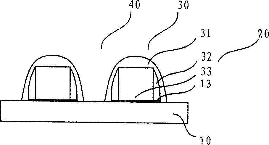
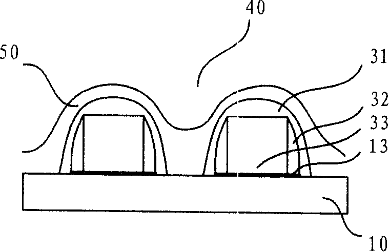
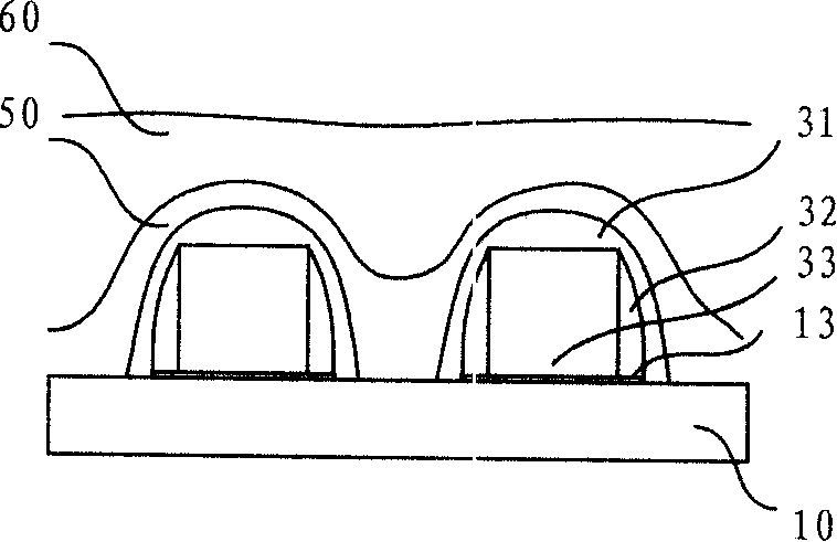
[0036] Although the invention will be described in more detail below with reference to the accompanying drawings, in which preferred embodiments of the invention are shown, it should be understood that those skilled in the art can modify the invention described herein and still achieve the advantageous effects of the invention. Therefore, the following description should be understood as a broad instruction for those skilled in the art, rather than as a limitation of the present invention.

[0037]In the interest of clarity, not all features of an actual implementation are described. In the following description, well-known functions and constructions are not described in detail since they would obscure the invention with unnecessary detail. It should be appreciated that in the development of any actual embodiment, numerous implementation details must be worked out to achieve the developer's specific goals, such as changing from one embodiment to another in accordance with sys...


PUM

PropertyMeasurementUnit
thicknessaaaaaaaaaa
thicknessaaaaaaaaaa
compressive stressaaaaaaaaaa

Abstract

The invention relates to a forming method for metal front dielectric layer, which comprises the following steps of: forming a metal front dielectric layer depositing substrate on a semi-conductor substrate; depositing a first metal front dielectric layer on the depositing substrate by using a first CVD method; and depositing a second metal front dielectric layer on the first metal front dielectric layer by using a second CVD method. The metal front dielectric layer without depositing cave can be formed to improve the performance of device by changing the internal stress state of device. The first dielectric layer is deposited by HARP SACVD technics, thus reducing the depth width ratio in subsequent manufacture process. Then, the second dielectric layer is deposited by using HDPCVD, SACVD, PECVD or other traditional technics to complete the depositing of the dielectric layer, thereby ensuring that the subsequent work is identical with the prior technics, reducing the change to the prior technics to the lowest for the purpose of technics optimization, and reducing development cost.

Description

technical field [0001] The invention relates to the technical field of integrated circuit manufacturing, in particular to a method for forming a pre-metal dielectric layer and its structure. Background technique [0002] The pre-metal dielectric layer (Pre-Metal Dielectric, PMD) is used as an isolation layer between the device and the interconnection metal layer and a protective layer to protect the device from impurity particles. The film deposition effect directly affects the performance of the device. [0003] With the gradual reduction of the size of semiconductor devices, the width of the slits to be filled during the deposition of the PMD layer is also getting smaller and smaller, and the aspect ratio is getting larger and larger. The ability to fill holes has become the optimization goal of the PMD layer deposition process. In the existing technology, high-density plasma chemical vapor deposition (HDPCVD) and subatmospheric pressure chemical vapor deposition (SACVD) p...

Claims


Application Information

Patent Timeline
Patent Type & Authority Applications(China)
IPC IPC(8): H01L21/31H01L21/00H01L23/532H01L23/00
Inventor 郑春生蔡明
Owner SEMICON MFG INT (SHANGHAI) CORP
Why Eureka
Try Eureka