
Earth-boring bits

A drill bit and roller cone technology, applied in the direction of drill bit, earthwork drilling, drilling equipment, etc., can solve the problems of drill bit corrosion and wear

Inactive Publication Date: 2008-06-11
ATI PROPERTIES +1
View PDF0 Cites 36 Cited by
  • Summary
  • Abstract
  • Description
  • Claims
  • Application Information

AI Technical Summary

Problems solved by technology

In addition, drilling soil filled with rock cuttings causes corrosive wear on the drill bit

Method used


Image

  • Earth-boring bits
  • Earth-boring bits
  • Earth-boring bits

Examples


Embodiment Construction

[0039] Embodiments of the invention relate to bit bodies for forming earth-boring drill bits, roller cones for roller cones, segmented roller cones, cone and tooth composites, and drill bits for making these articles method of the subject. Additionally, the method can be used to make other articles. Certain embodiments of the present drill bit bodies include at least one discontinuous hard phase and a continuous binder phase bonded together with the hard phase. Embodiments of the compositions and methods of the present invention provide increased service life and thereby improved The useful life of an earth-boring drill bit or other tool. The body material of the bit body, roller cone, insert roller cone, cone provides an integral character to each area of ​​the article.

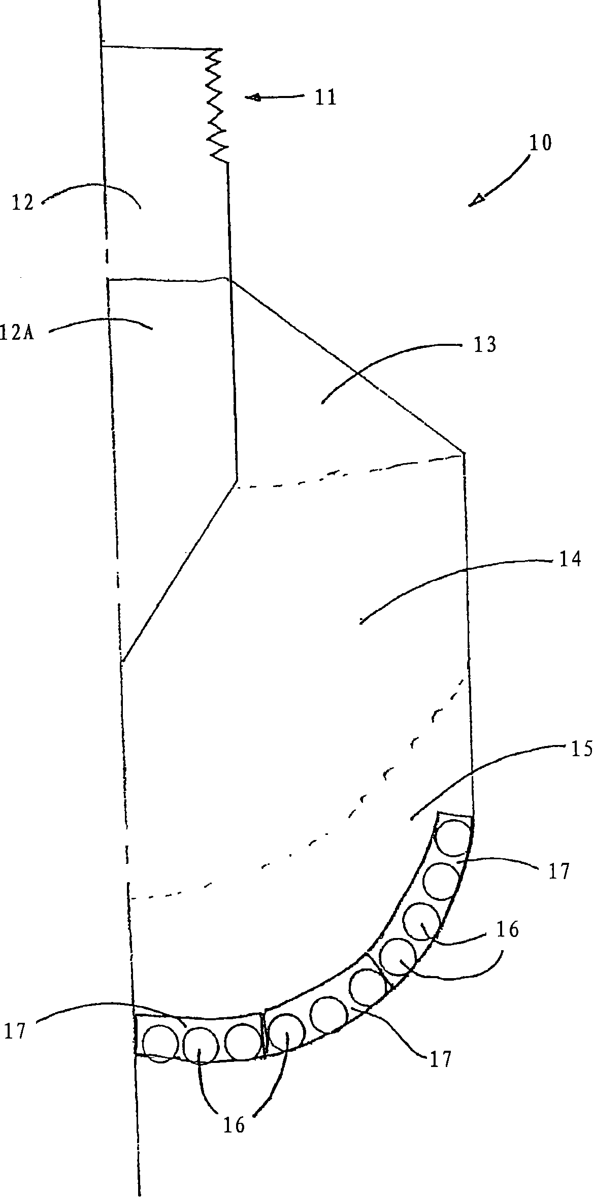
[0040] figure 1 A typical drill bit body 10 is shown for earth boring with fixed cutters. In general, the drill body 10 includes an attachment means 11 on the shank 12 and a blank area 12A incorporated ...


PUM

PropertyMeasurementUnit
melting pointaaaaaaaaaa
breaking strengthaaaaaaaaaa

Abstract

The present invention relates to compositions and methods for forming a bit body for an earth-boring bit. The bit body may comprise hard particles, wherein the hard particles comprise at least one carbide, nitride, boride, and oxide and solid solutions thereof, and a binder binding together the hard particles. The binder may comprise at least one metal selected from cobalt, nickel, and iron, and, optionally, at least one melting point reducing constituent selected from a transition metal carbide in the range of (30) to (60) weight percent, boron up to (10) weight percent, silicon up to (20) weight percent, chromium up to (20) weight percent, and manganese up to (25) weight percent, wherein the weight percentages are based on the total weight of the binder. In addition, the hard particles may comprise at least one of (i) cast carbide (WC + WC) particles, (ii) transition metal carbide particles selected from the carbides of titanium, chromium, vanadium, zirconium, hafnium, tantalum, molybdenum, niobium, and tungsten, and (iii) sintered cemented carbide particles.

Description

technical field [0001] The present invention relates to an earth-boring bit and a method of producing an earth-boring bit. More particularly, the present invention relates to an earth-boring bit body, a roller cone, an insert roller cone, a cone and teeth for a roller cone earth-boring bit and forming an earth-boring bit Bit body, roller cone, insert roller cone, cone and tooth method for a roller cone earth-boring bit. [0002] This application is a continuation-in-part of US Patent Application No. 10 / 848437, filed May 18, 2004, which claims priority from US Provisional Application No. 60 / 556063, filed April 28, 2004. Background technique [0003] Earth-boring bits can have fixed or rotatable cutting elements. Earth-boring bits with fixed cutting elements typically include a bit body either by machining from steel or by infiltrating a binder such as a copper-based alloy into a carbide such as cast carbide (WC+W 2 C), tungsten carbide (WC) and / or sintered hard particle ...

Claims


Application Information

Patent Timeline
Patent Type & Authority Applications(China)
IPC IPC(8): E21B10/46C22C1/10C22C29/00C22C29/06E21B10/00
CPCC22C29/005C22C29/067C22C1/1068B22F2005/001
Inventor 普拉卡什·K·米尔钱达尼吉米·W·伊森詹姆斯·J·奥克斯詹姆斯·C·韦斯索夫加布里埃尔·B·科林斯史蒂文·G·考德威尔约翰·H·史蒂文斯艾尔弗雷德·J·莫斯科
Owner ATI PROPERTIES
Learn More