Polarizing plate and display device

A technology for display devices and polarizers, applied in optics, optical elements, polarizing elements, etc., which can solve problems such as easy mixing of air bubbles, difficulty in reducing the weight of polarizers, and deviation of bonding positions

Active Publication Date: 2008-06-11
KONICA MINOLTA OPTO
View PDF28 Cites 10 Cited by
  • Summary
  • Abstract
  • Description
  • Claims
  • Application Information

AI Technical Summary

Problems solved by technology

However, in the described method, in order to impart a desired birefringence value, it is necessary to increase the film thickness, and it is difficult to reduce the film thickness of the polarizer to reduce the weight.
[0006] In these described methods, it is obvious that when the polarizer protective film or the film thickness of the polarizer is thinned and the film polarizer whose total film thickness of the polarizer is reduced is attached to a large liquid crystal panel, air bubbles are easy to be mixed due to curling or deformation. The problem of prone to positional deviation failures during lamination

Method used

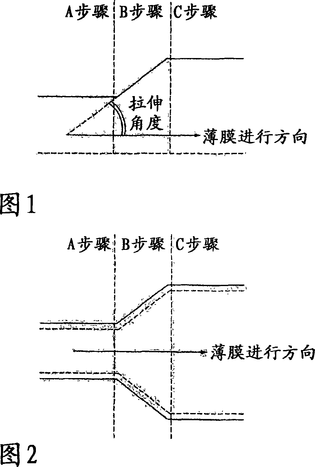

Image

  • Polarizing plate and display device
  • Polarizing plate and display device
  • Polarizing plate and display device

Examples


Embodiment 1

[0386] Production of Polarizer Protective Film A

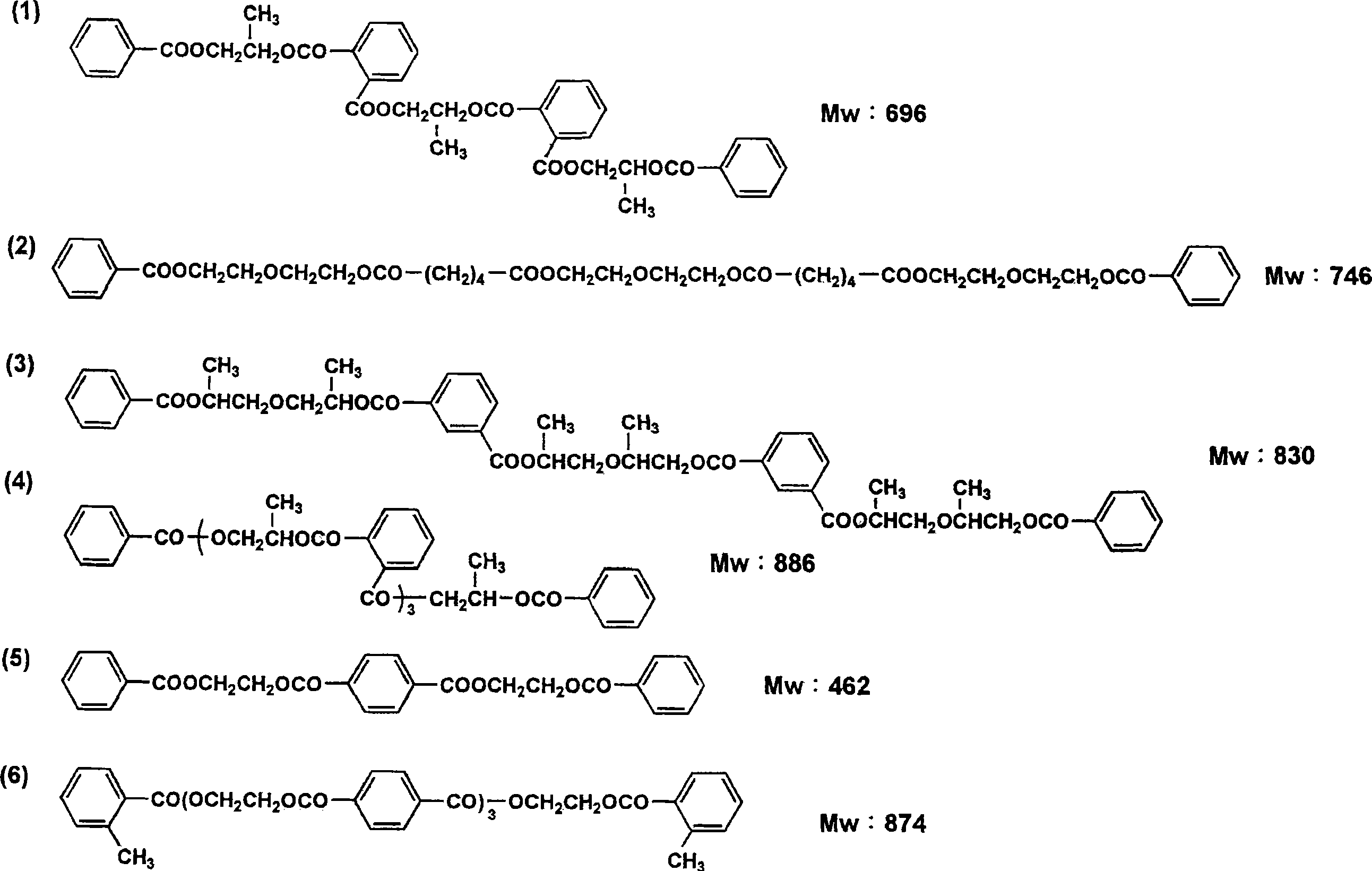
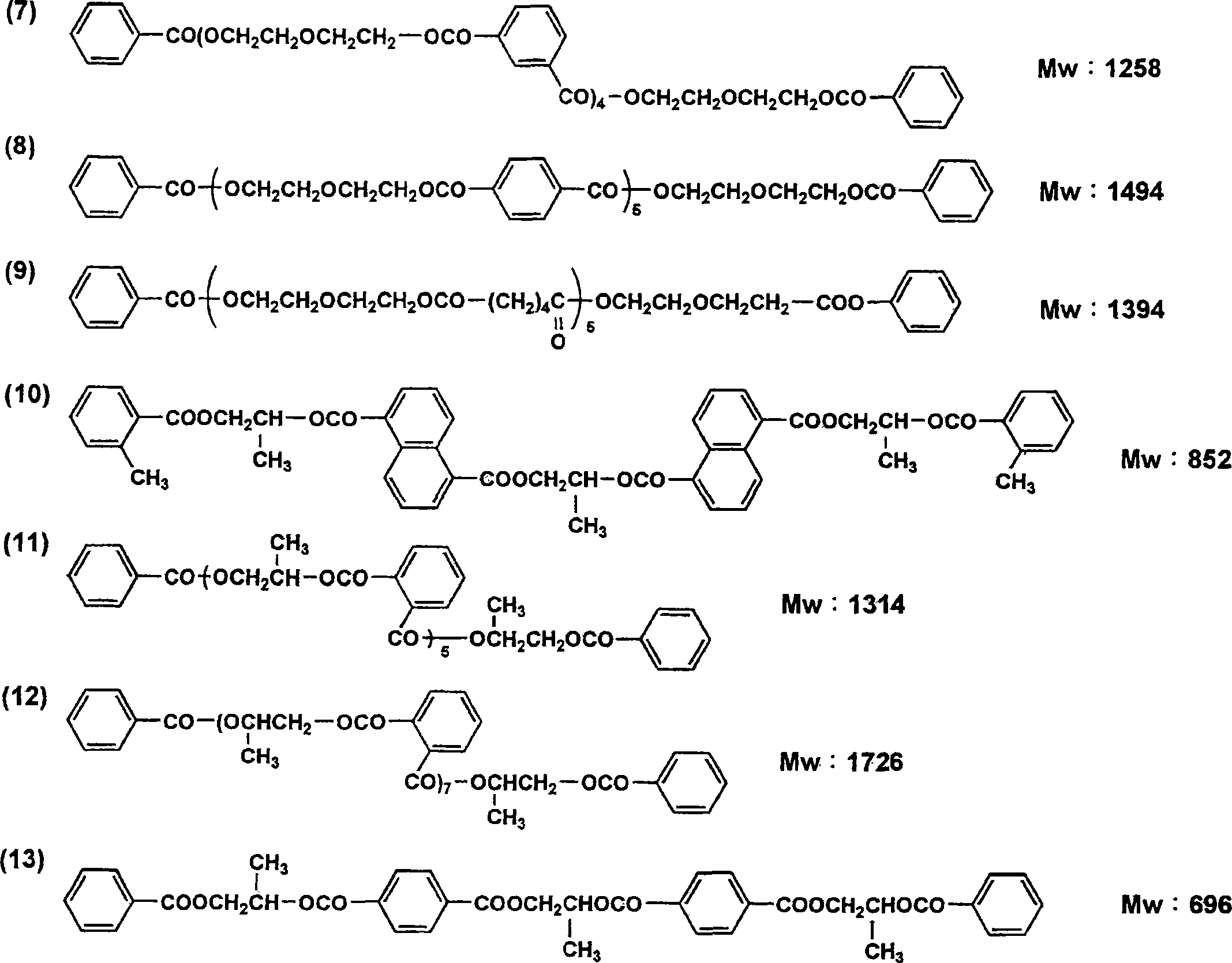
[0387] The used plasticizers and UV absorbers are shown in Table 1.

[0388] In Table 1, UV absorber 1 can be synthesized by the following synthesis recipe.

[0389]

[0390] 2(2'-hydroxy-5'-tert-butyl-phenyl)-5-(2'-methacryloyloxy)ethoxycarbonyl-2H-benzotriazole (exemplary compound MUV-19), according to synthesized by the method described below.

[0391]20.0 g of 3-nitro-4-amino-benzoic acid was dissolved in 160 ml of water, and 43 ml of concentrated hydrochloric acid was added. After adding 20 ml of 8.0 g of sodium nitrite dissolved in water at 0°C, it was stirred at 0°C for 2 hours. This solution was added dropwise at 0°C while dissolving 17.3 g of 4-tert-butylphenol in 50 ml of water and 100 ml of ethanol, while keeping the liquidity alkaline with potassium carbonate. The solution was kept at 0°C for 1 hour, and then stirred at room temperature for 1 hour. The reaction solution was made acidic with hydrochloric acid...

Embodiment 2

[0493] (Production of optical film with anti-reflection layer)

[0494] Using the cellulose ester film 301 produced above as the polarizer protective film A, an optical film with an antireflection layer was produced in the following procedure.

[0495] The refractive index of each layer constituting the antireflection layer was measured by the following method.

[0496] (refractive index)

[0497] The refractive index of each refractive index layer was calculated|required from the measurement result of the spectral reflectance with a spectrophotometer with respect to the sample which coated each layer individually on the hard coat film produced below. The spectrophotometer uses U-4000 type (manufactured by Hitachi, Ltd.). After the inner surface of the sample measurement side is roughened, it is treated with black spray to prevent light reflection on the inner surface. The measurement of the reflectance in the visible light region (400nm ~ 700nm) is carried out under the con...


PUM

PropertyMeasurementUnit
thicknessaaaaaaaaaa
hardnessaaaaaaaaaa
thicknessaaaaaaaaaa

Abstract

Disclosed is a polarizing plate composed of a polarizer and two polarizing plate protecting films A, B sandwiching the polarizer. This polarizing plate is characterized in that the two polarizing plate protecting films A, B respectively have a thickness of 30-60 m, and the film B has an in-plane retardation Ro of 20-100 nm and a retardation in the thickness direction Rt of 10-300 nm. The polarizing plate is further characterized by having a thickness of 80-160 m, and a stiffness (ST) of 20-80 (g) at 23 DEG C, 55% RH.

Description

technical field [0001] The present invention relates to a polarizer and a display device. More specifically, it relates to a polarizer that can reduce light leakage and reduce failures when the polarizer is attached to a display panel and a display device using the polarizer. Background technique [0002] In order to alleviate the mass increase accompanying the weight reduction of electronic equipment and the increase in size of liquid crystal display devices, it is required to reduce the thickness of polarizers. However, once the size of the liquid crystal display device is increased, it becomes difficult to attach the polarizer to the liquid crystal cell due to curling or deformation. [0003] For example, Patent Document 1 proposes a polarizer using a thin-film polarizer, which may exhibit little curl or deformation. However, this method has a problem of deterioration in productivity because it is greatly different from conventional polarizer manufacturing steps. Moreov...

Claims


Application Information

Patent Timeline
Patent Type & Authority Applications(China)
IPC IPC(8): G02B5/30G02F1/1335
CPCG02B5/3025G02B5/3083C09K2323/031C09K2323/035C09K2323/057G02B5/30
Inventor 稻垣真治梅田博纪葛原宪康
Owner KONICA MINOLTA OPTO
Why Eureka
Try Eureka