Laser edge banding machine for plastic film, nonwoven cloth composite filter paper

A technology of plastic film and non-woven fabric, applied in the field of filter element manufacturing, can solve the problems of low efficiency, high cost, limited speed of hot-pressing edge sealing, etc., and achieve the effect of reducing manufacturing cost, high penetration rate and increasing output

Inactive Publication Date: 2008-07-02
武汉楚天激光(集团)股份有限公司
View PDF0 Cites 12 Cited by
  • Summary
  • Abstract
  • Description
  • Claims
  • Application Information

AI Technical Summary

Problems solved by technology

[0003] 1. The principle of hot pressing edge sealing is single-sided heat conduction, which causes the contact surface of plastic and non-woven fabric to self-melt, and is formed by mutual adhesion under pressure. In this way, when heat is transferred from the outside to the contact surface of the two films, It takes time, therefore, its efficiency is relatively low
[0004] 2. Due to the above reasons, conduction heating will also make the instantaneous heat distribution of the film section not very ideal. What we need is the contact surface of the two films to produce a molten state. However, since the heat is conducted from the outside, the hottest surface But on the outside, when the temperature is raised, it may cause a large area of ​​the film to be hot-collapsed. Therefore, it is generally necessary to heat it below the critical temperature. At the same time, it must be pressed with a roller to force the two layers of film to be hot-melt bonded.
[0006] Even so, it is still difficult to guarantee 100% no side leakage. If there is side leakage, it means that the purity of seawater desalination is not enough
In addition, the filter element is a consumable, the demand is very large, and it is required to achieve a considerable production capacity. The current hot-press edge banding has a limited speed, and the increase in production can only be achieved by adding equipment, and the cost is quite high.

Method used


Image

  • Laser edge banding machine for plastic film, nonwoven cloth composite filter paper
  • Laser edge banding machine for plastic film, nonwoven cloth composite filter paper
  • Laser edge banding machine for plastic film, nonwoven cloth composite filter paper

Examples


Embodiment Construction

[0032] The following examples are used to illustrate the present invention, but not to limit the scope of the present invention.

[0033] See Figure 4 , Figure 5 , Figure 6 , The laser edge banding machine used for plastic film and non-woven composite filter paper of the present invention is mainly composed of servo drive motor 3, winding roller 4, focusing system 5, smoking device 6, laser 7, passing roller 8, working Roller 19, tension sensor 9, laser translation rail 10, control cabinet 11, unwinding roller 12, magnetic powder brake 13, left and right wall panels 14, machine base 15, gantry 16, work roll bracket 17, loading and unloading clutch 18 composition.

[0034] The passing roller 8 is installed on the left and right large wall panels 14, the middle passing roller 8 is supported on the tension sensor 9, and the working passing roller bracket 17 is installed on the front gantry 16 to support the working passing roller 19.

[0035] The winding roller 4 and the unwinding ...


PUM


Abstract

The invention relates to a filter core manufacture field. The invention discloses a laser edge bonding machine used for plastic films and non-woven fabrics composite filter paper. The invention comprises a laser device, a composite filter paper transmission device, a bracket system, a smoke pumping device and a loading/unloading device. The laser device and the composite filter paper transmission device are supported by the bracket system; the laser device is arranged above the composite filter paper transmission device; the smoke pumping device is arranged above the composite filter paper transmission device and below the laser device; the loading/unloading device is arranged on the side surface of the bracket system. The edge bonding heating of the invention has the advantages of high efficiency, high processing speed and simple structure.

Description

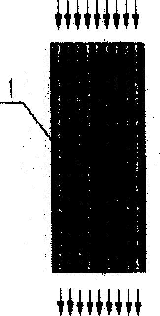
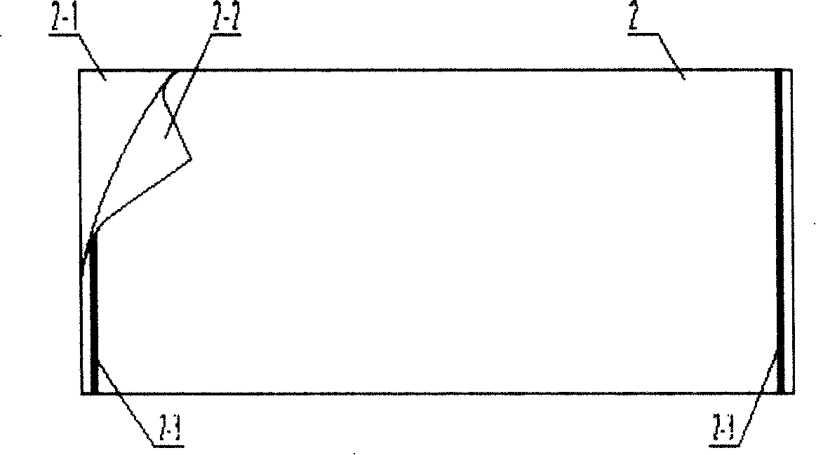
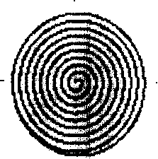
Technical field [0001] The invention relates to the field of filter element manufacturing, in particular to a laser edge banding machine for plastic film and non-woven composite filter paper. Background technique [0002] "Plastic film + non-woven composite filter element" is an important part of the seawater desalination device. The filter element is rolled into a cylindrical shape by "plastic film + non-woven composite filter paper" (see Figure 1), Figure 1a It is the finished product of the rolled filter element, Figure 1b Is the top view of the filter element, Figure 1c It is an expanded view. In the unfolded drawing, (2-1) is a non-woven fabric, (2-2) is a plastic film, and (2-3) is an edge sealing line to prevent side leakage. At present, the edge banding line of the imported production line equipment in my country is currently used for hot-pressing edge banding. See the shape after edge banding. image 3 ,in image 3 Medium: (2-3) is the cross-sectional shape after edge...

Claims


Application Information

Patent Timeline
Patent Type & Authority Applications(China)
IPC IPC(8): B29C65/16B29C65/78B23K26/16B23K26/04B23K26/08B65H20/02B65H16/00B65H18/00B65H77/00B01D39/08
CPCB29L2031/14
Inventor 韩小平熊明富孙文
Owner 武汉楚天激光(集团)股份有限公司
Why Eureka
Try Eureka