Non-mask write through photo-etching machine with ultrahigh strength LED light source

An LED light source and ultra-high-intensity technology, which can be used in micro-lithography exposure equipment, photo-plate-making process exposure devices, etc., can solve problems such as insufficient energy of light-emitting diodes

Inactive Publication Date: 2008-07-30
HEFEI ADVANTOOLS SEMICON
View PDF0 Cites 16 Cited by
  • Summary
  • Abstract
  • Description
  • Claims
  • Application Information

AI Technical Summary

Problems solved by technology

[0010] In order to solve the problem of insufficient energy of a single light-emitting diode used as a light source in today's lithography machines, the present invention provides a m

Method used


Image

  • Non-mask write through photo-etching machine with ultrahigh strength LED light source
  • Non-mask write through photo-etching machine with ultrahigh strength LED light source

Examples


Embodiment 1

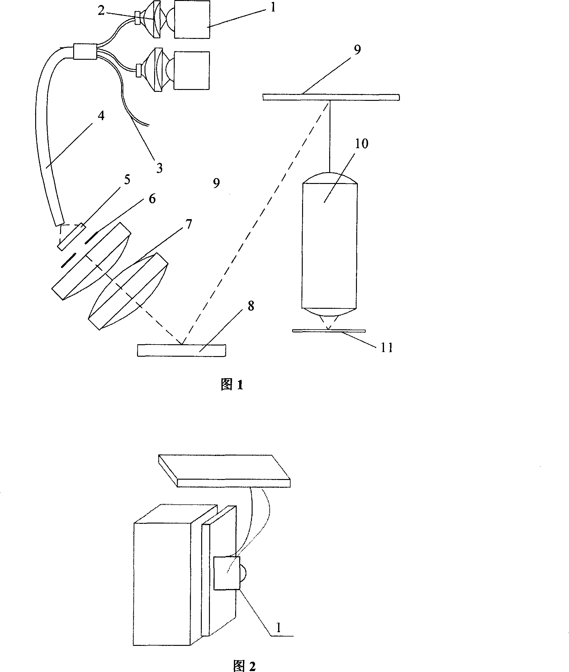
[0027] A maskless direct writing lithography machine with an ultra-high-intensity LED light source includes a light source, an aperture stop 6, a relay objective lens 7, a mirror 8, a digital mask plate 9, a projection objective lens 10, and a wafer table 11; the light source is a light emitting The diode light source, the light source aperture diaphragm 6 and the relay objective lens 7 are located on the same axis, and correspond to the mirror 8, and the mirror 8 corresponds to the DMD digital mask 9 on one side, and the DMD digital mask 9 passes through the projection below it The objective lens 10 corresponds to the wafer surface 11 .

[0028] The light source includes two light-emitting diodes 1; each light-emitting diode corresponds to a condenser lens 2, and the rear of each condenser lens 2 is respectively connected to a coupling fiber 3, and the coupling fiber 3 is connected to a core-changing fiber 4, and the core-changing fiber 4 The other end corresponds to the cohe...

Embodiment 2

[0033] The light source includes three light emitting diodes 1;

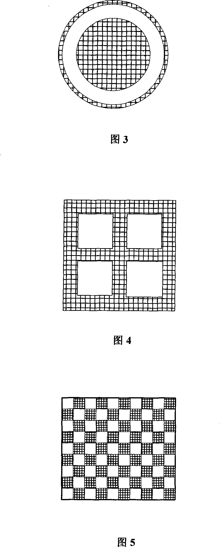
[0034] The coherent plate 5 is a quadrupole illuminated coherent plate, as shown in FIG. 4 .

[0035] Other structures are with embodiment 1.

Embodiment 3

[0037] The light source includes four light emitting diodes 1;

[0038] The coherent film 5 is a binary grating illumination coherent film, as shown in FIG. 5 .

[0039] Other structures are with embodiment 1.


PUM


Abstract

The invention relates to a maskless direct-writing photoetching machine with ultrahigh-intensity LED light sources for printing on substrate materials such as a wafer and a printed circuit board. The invention solves the problems that the intensity of single light emitting diode can not meet the requirements for illuminating low-range large-field area maskless photoetching machines. The machine comprises more than two LEDs as light sources, wherein each LED is arranged relative to one condensing lens and the back part of each LED is connected in order with a coupling optical fiber and a tapered optical fiber which is arranged relative to a coherence sheet. The more than two LEDs are used as light sources for the direct-writing photoetching machine and can emit lights at the same time. The light-guide optical fibers can independently correct optical energy to increase the light intensity of the LEDs by means of spatial arrangement and coupling.

Description

technical field [0001] The invention relates to equipment for printing patterns on substrate materials such as wafers, printed circuit boards, mask plates, flat panel displays, biological wafers, micromechanical electronic wafers, and optical glass plates, that is, direct writing photolithography machines. Background technique [0002] The exposure light source part of the lithography machine is one of the important components of various proximity, step-and-repeat, and step-scan lithography machines. Its light intensity, life, uniformity, and calorific value are directly related to the design of other components. relevant. The light source affects the quality of the final key feature size used by the lithography machine, the use and maintenance costs and other issues. Judging from the current products of major lithography machine suppliers, in lithography machines with a lithography resolution of 0.28 μm or more, the ultra-high pressure mercury lamp is mainly used as the li...

Claims


Application Information

Patent Timeline
IPC IPC(8): G03F7/20
Inventor 张东涛
Owner HEFEI ADVANTOOLS SEMICON
Why Eureka
Try Eureka