Alloy composition for lithium ion batteries
A technology of lithium ion battery and composition, applied in battery electrodes, circuits, electrical components, etc., can solve problems such as reduction of electrical contact capacity
- Summary
- Abstract
- Description
- Claims
- Application Information
AI Technical Summary
Problems solved by technology
Method used
Image

Examples
Embodiment 1
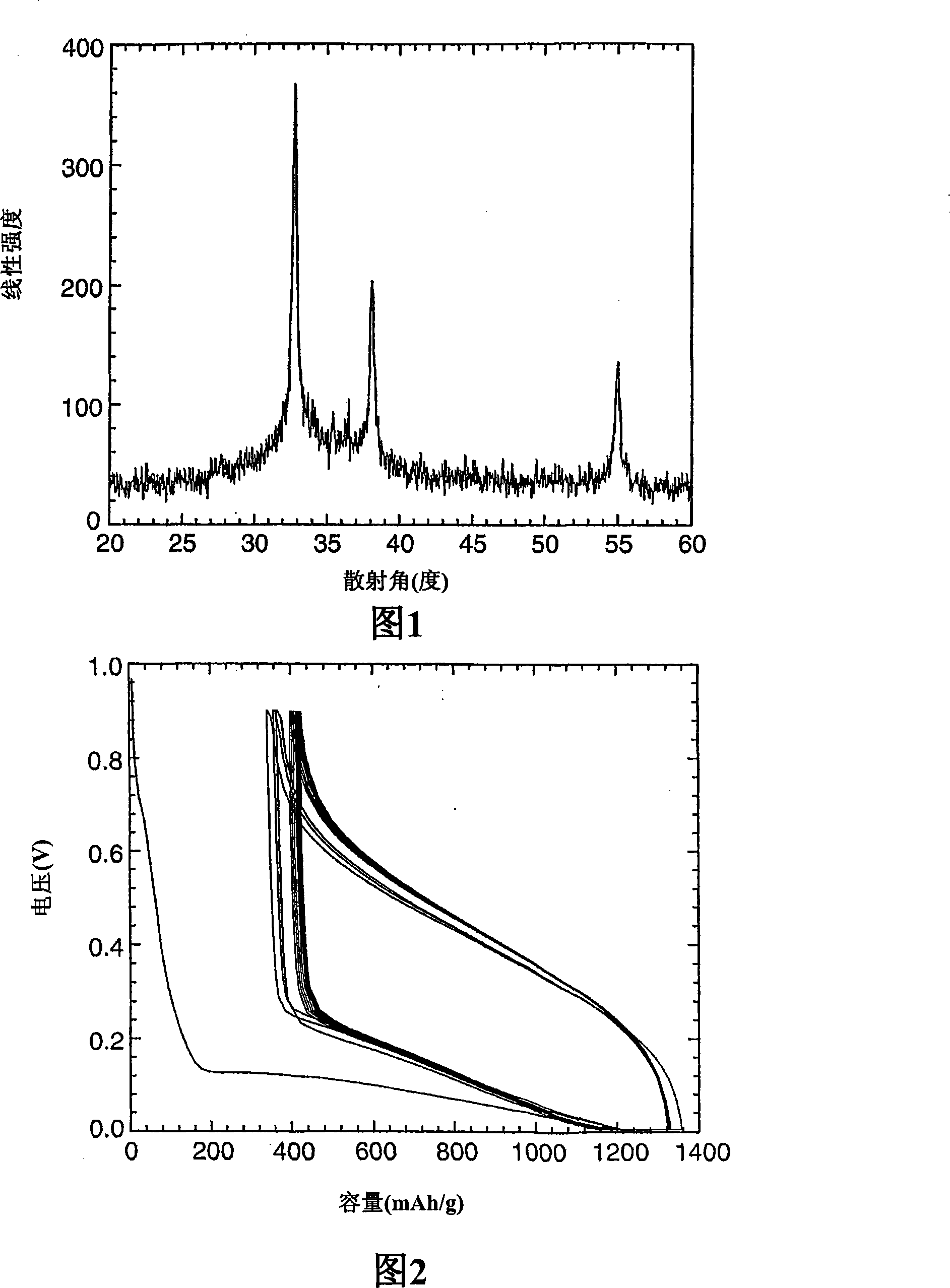
[0094] Example 1: Si 60 Al 14 Fe 8 TiInSn 6 (MM) 10
[0095] Alloy composition Si 60 Al 14 Fe 8 TiInSn 6 (MM) 10 Prepared by mixing: 17.606g of silicon wafers, 3.947g of aluminum pellets, 4.668g of iron nuggets, 0.500g of sponge titanium, 7.441g of tin pellets, 1.200g of indium and 14.639g of misch metal nuggets . The mixture was fused together on a carbon hearth in an argon-filled electric arc furnace from Advanced Vacuum Systems, Ayer, MA. The resulting ingot has the composition Si 60 Al 14 Fe 8 TiSn 6 In Mm, the ingot was broken into pieces measuring about 1 cm in all directions.
[0096]The ingot was then further processed by melt spinning in a melt spinning apparatus comprising a vacuum chamber with a cylindrical quartz glass crucible (16 mm inner diameter and 140 mm length) with 0.35 mm holes located above the rotating cooling wheel. The rotating cooling wheel (10mm thick and 203mm diameter) is made of copper alloy (Ni-Si-Cr-Cu C18000 alloy, 0.45wt% chro...
Embodiment 2
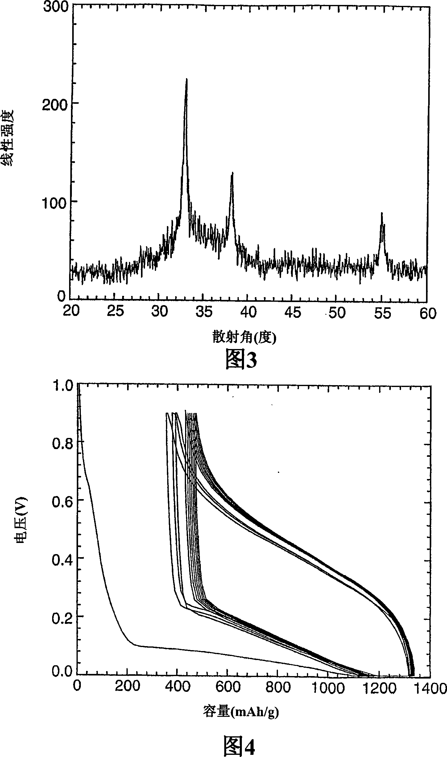
[0102] Example 2: Si 60 al 14 Fe 8 TiIn 3 sn 4 (MM) 10
[0103] Using a procedure similar to that in Example 1, the alloy composition Si was prepared by mixing 60 al 14 Fe 8 TiIn 3 sn 4 (MM) 10 : 17.634g of silicon wafer, 3.953g of aluminum shot, 4.675g of iron block, 0.501g of sponge titanium, 4.969g of tin shot, 3.605g of indium and 14.663g of misch metal. The resulting melt-spun ribbon was annealed by heating at 200° C. for 2 hours under flowing argon. Figure 3 shows the XRD pattern.
[0104] The resulting alloy composition was tested in the electrochemical cell described in Example 1. Electrochemical cells were prepared using the procedure described in Example 1. The voltage versus capacity curve for this material is shown in FIG. 4 . The reversible specific capacity is 950mAh / g.
Embodiment 3
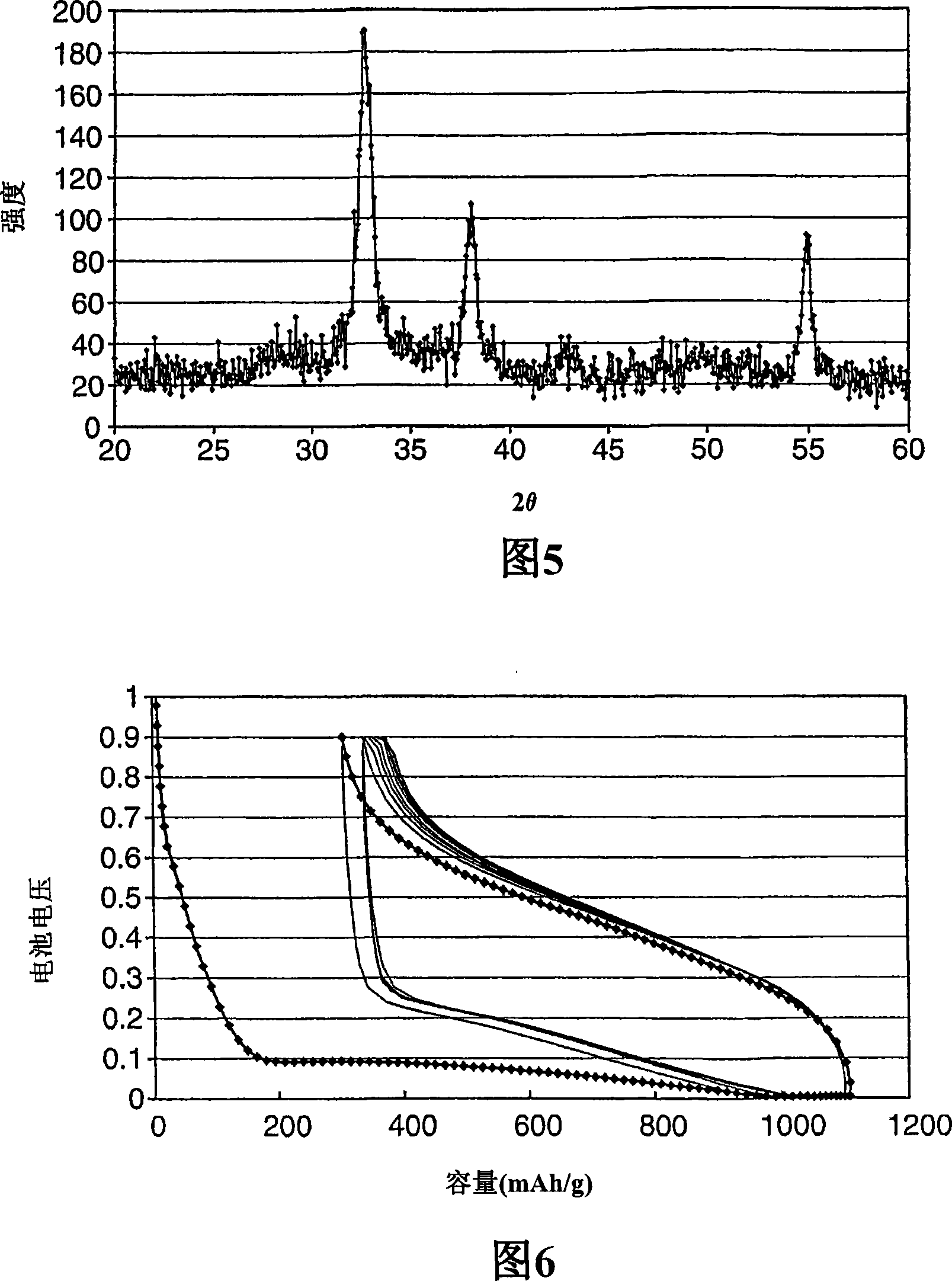
[0105] Example 3: Si 59 al 16 Fe 8 In 1 sn 6 (MM) 10
[0106] Using a procedure similar to that in Example 1, the alloy composition Si was prepared by mixing 59 al 16 Fe 8 In 1 sn 6 (MM) 10 : 9.062g aluminum, 34.785g silicon, 9.379g iron, 2.410g indium, 14.949g tin and 29.414g misch. Melt spinning was performed at 1350°C.
[0107] 10 g of the melt-spun ribbon were annealed at 200° C. for 2 hours in a tube furnace under argon flow. The XRD pattern of the resulting alloy composition is shown in FIG. 5 .
[0108] To a 40 ml tungsten carbide grinding vessel comprising 2 carbide balls of 10 mm diameter and 10 tungsten carbide balls of 3 mm diameter were added the following components: 1.70 g of the upper melt-spun ribbon, 100 mg of SUPER P carbon (available from MMM Carbon , Belgium), 1.0 g of polyimide coating solution (commercially available from HD Microsystems, Cheesequake Rd, Parlin, NJ, trade name PYRALIN PI2555, 20 wt % N-methyl-2-pyrrolidone solution) and 5.2 ...
PUM
| Property | Measurement | Unit |
|---|---|---|
| Diameter | aaaaa | aaaaa |
| Width | aaaaa | aaaaa |
| Thickness | aaaaa | aaaaa |
Abstract
Description
Claims
Application Information
 - R&D Engineer
- R&D Manager
- IP Professional
- Industry Leading Data Capabilities
- Powerful AI technology
- Patent DNA Extraction
Browse by: Latest US Patents, China's latest patents, Technical Efficacy Thesaurus, Application Domain, Technology Topic.
© 2024 PatSnap. All rights reserved.Legal|Privacy policy|Modern Slavery Act Transparency Statement|Sitemap