Arc-extinction electric contact part based on micro-electronic mechanical technology

A micro-electronic mechanical and electrical contact technology, applied in the direction of electrical components, circuits, electrical switches, etc., can solve the problems of reducing reliability and arc extinguishing ability, reducing device yield, increasing manufacturing cost, etc. The effect of low loss and simple process

Inactive Publication Date: 2008-08-06
SHANGHAI JIAO TONG UNIV
View PDF1 Cites 9 Cited by
  • Summary
  • Abstract
  • Description
  • Claims
  • Application Information

AI Technical Summary

Problems solved by technology

Its closed upper electrode structure is not conducive to heat dissipation, which will greatly reduce reliability and arc extinguishing ability
The structural design of the upper and lower parts will not only reduce the yield of the device, but also increase the cost
Bulk silicon processes limit the diversity of structural and electrical contact material choices, reducing reliability while increasing manufacturing costs

Method used


Image

  • Arc-extinction electric contact part based on micro-electronic mechanical technology
  • Arc-extinction electric contact part based on micro-electronic mechanical technology

Examples


Embodiment 1

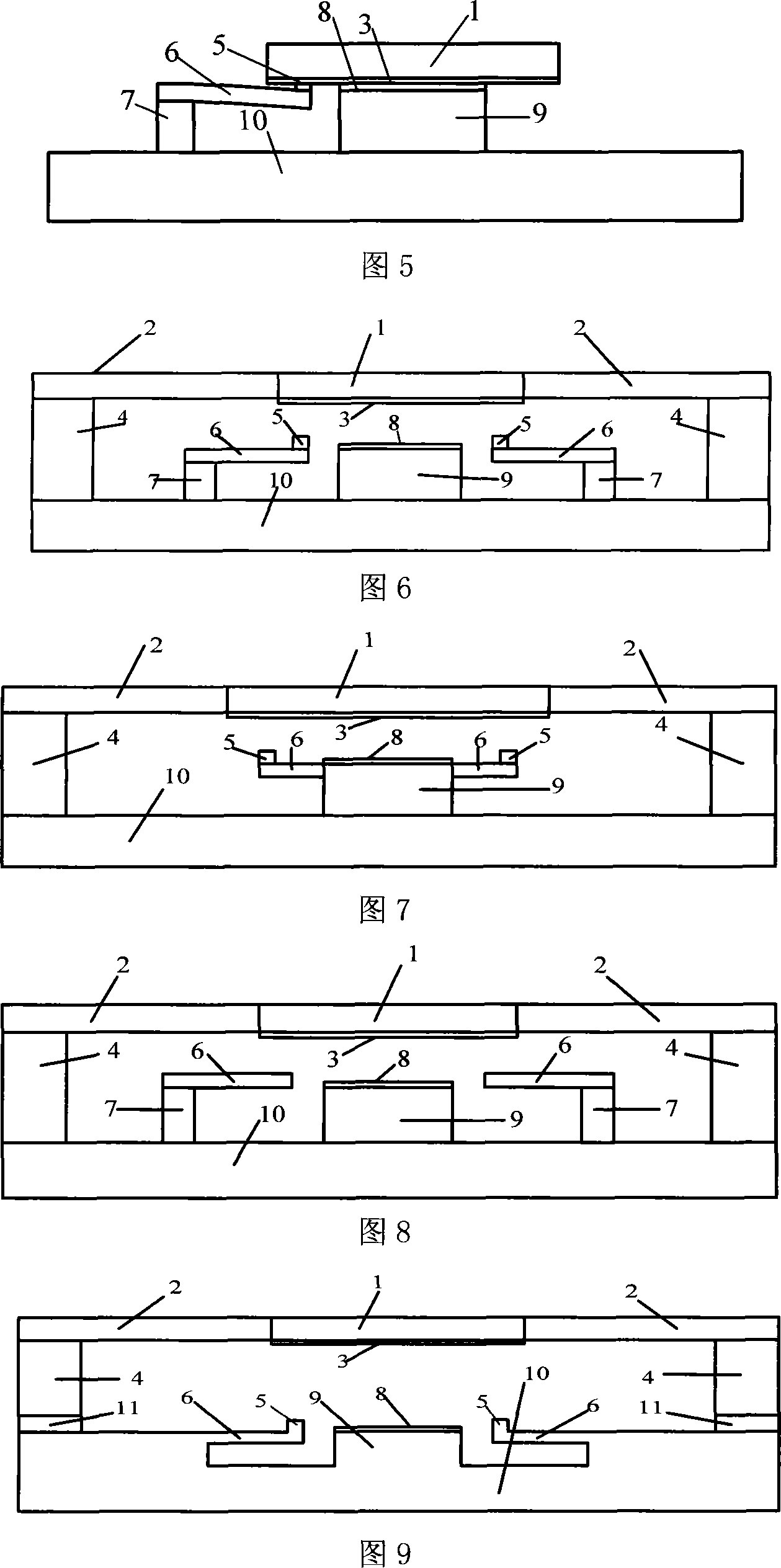
[0051] As shown in FIG. 6 , the height of the cantilever beam 6 is the same as that of the lower electrode 9 , and the auxiliary contact 5 is formed on the cantilever beam 6 . The on-off time difference between the auxiliary contact 5 and the main contact 8 is realized by the height of the auxiliary contact 5. The number of current limiting resistors and cantilever beams 6 are both 24, the resistance value is 240Ω, the upper electrode 1, the support body 2, the connecting column 4, The cantilever beam 6, the cantilever beam support 7 and the lower electrode 9 are all made of nickel; the substrate structure 10 is glass; the upper electrode contact 3, the auxiliary contact 5 and the main contact 8 are all made of gold; and the resistor is made of titanium. The specific implementation method is as follows: firstly sputter a 500nm titanium film on the glass sheet, then pattern the resistor by RIE dry etching or HF wet etching, secondly sputter a Cu / Cr seed layer with a thickness of...

Embodiment 2

[0053] As shown in FIG. 7 , the auxiliary contact 5 is still used to realize the successive on-off of the auxiliary contact 5 and the main contact 8 . The number of current limiting resistors and the cantilever beams 6 are both 80 and the resistance value is 80Ω. The difference from the structure of the first embodiment shown in FIG. 6 is that the cantilever beams 6 and the lower electrode 9 are fabricated together. The materials used are also different, the support body 2 is made of SU-8 glue; the upper electrode 1, the connecting column 4, the cantilever beam 6 and the cantilever beam support 7 are all made of nickel; the lower electrode 9 is made of copper; the substrate structure 10 is a silicon wafer; The upper electrode contact 3 is made of silver-palladium alloy; the auxiliary contact 5 and the main contact 8 are made of gold-nickel alloy; and the resistor is made of chromium. The specific implementation method is as follows: firstly, a silicon dioxide insulating layer ...

Embodiment 3

[0055] As shown in FIG. 8 , by increasing the height of the cantilever beam support 4 or the height of the cantilever beam 6 to realize the successive on-off of the auxiliary contact 5 and the main contact 8, the number of the current limiting resistor and the cantilever beam 6 are both 100, and the resistance value 300Ω. Only examples of the heightened cantilever beam support 4 are listed below. The cantilever beam 6 is slightly higher than the lower electrode 9 , and the cantilever beam 6 itself serves as the auxiliary contact 5 . The on-off time difference between the auxiliary contact 5 and the main contact 8 is realized by the height difference between the cantilever beam 6 and the lower electrode 9 . The upper electrode 1 is made of iron-nickel alloy, and the lower electrode 9 is made of copper; the support body 2 is made of polyimide; the connecting column 4 and the cantilever beam support 7 are made of iron-nickel alloy; the cantilever beam 6 is made of nickel; the su...


PUM


Abstract

The invention discloses a blow-out electric contactor element on the basis of the microelectronic mechanical technology, belonging to the microelectronic mechanical technical field. The invention comprises an upper part and a lower part, wherein, the upper part structure and the lower part structure are combined into a whole through a through hole connecting terminal manufactured integrally to form an electric contactor element body. The upper structure comprises a support body and an upper electrode and contacts of the upper electrode; the lower part structure comprises an underlay structure on which a lower electrode corresponding to the upper electrode and auxiliary contacts are arranged; the lower electrode serves as a main contact; all auxiliary contacts and the main contact are connected in parallel; the auxiliary contacts are realized by a socle beam structure; each auxiliary contact is connected in series with a current-limiting resistance; resistance value and number of parallel connected resistance are selected to prevent arc starting of the auxiliary contacts. The auxiliary contacts bear the energy of disjunction or closing, so that the main contact can work under the smallest striking voltage and avoid arc starting of the main contact, thereby realizing nonarcing make-and-break of a circuit.

Description

technical field [0001] The invention relates to a device in the technical field of micro-electro-mechanical systems, in particular to an arc-extinguishing electrical contact device based on micro-electro-mechanical technology. Background technique [0002] With the advancement of science and technology, the miniaturization trend of electrical contact components such as contactors, circuit breakers, and contactor-circuit breakers is becoming more and more obvious. Technology presents unprecedented challenges. The development of reliable miniature electrical contact elements has become a major issue in the industry. In the past ten years, based on the special process unique to large-scale integrated circuit manufacturing technology and micromachining technology, the multifunctional integration of micromechanical structures, microactuators, microelectronic devices and circuit systems has been realized, forming the so-called microelectronics. Mechanical systems (MEMS for short...

Claims


Application Information

Patent Timeline
Patent Type & Authority Applications(China)
IPC IPC(8): H01H9/30H01H9/42
Inventor 丁桂甫周建胜杨卓青刘瑞
Owner SHANGHAI JIAO TONG UNIV
Why Eureka
Try Eureka