

A built-in permanent magnetic brushless DC motor control system for no position sensor
A permanent magnet brushless DC, motor control technology, applied in the control system, electronic commutation motor control, single motor speed/torque control, etc., can solve problems such as failure
- Summary
- Abstract
- Description
- Claims
- Application Information
AI Technical Summary
Problems solved by technology
Method used
Image

Examples
Embodiment Construction
[0103] The implementation of the present invention will be described in detail below in conjunction with the accompanying drawings.
[0104] Description of the hardware part
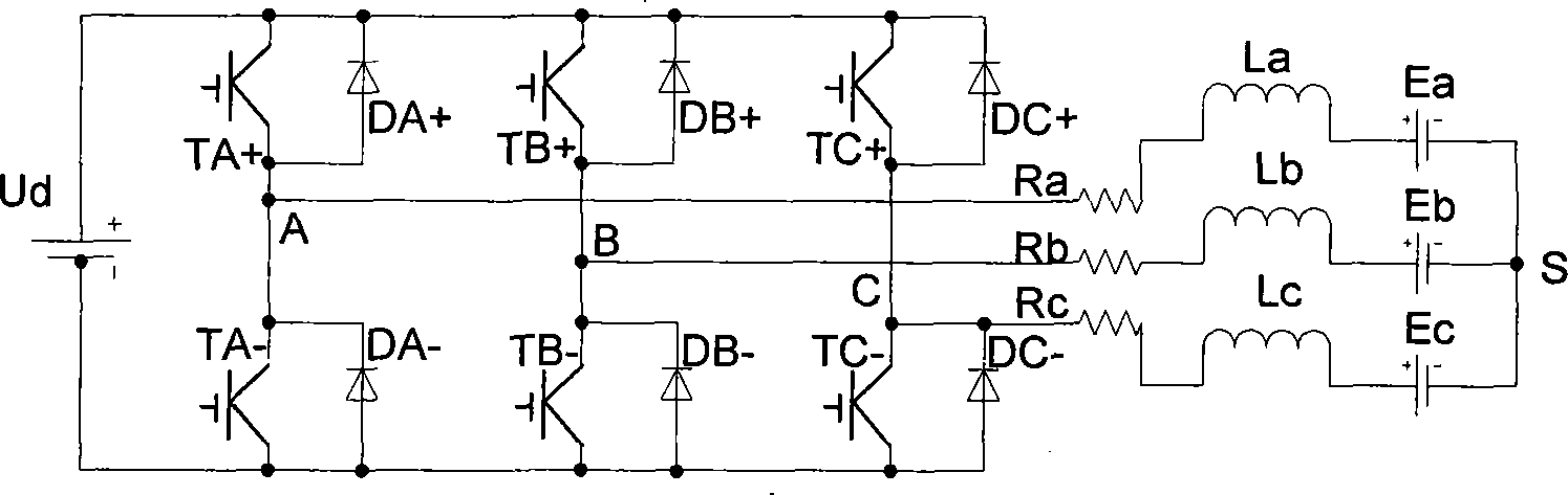
[0105] Such as Figure 9As shown, an embedded permanent magnet brushless DC motor control system without a position sensor consists of a microprocessor controller 1, an IPM module, a drive unit 2, a current detection circuit 3, a phase voltage detection circuit 4, and an output display circuit 5. Control input circuit 6, permanent magnet brushless DC motor with embedded rotor structure 7, drive and control power supply 8 and fault detection and protection circuit 9; microprocessor controller 1 calculates according to the detected voltage and current signals The position signal of the rotor is generated to generate six PWM control signals; after the PWM control signal is transformed by the IPM module and the drive unit 2, a high-voltage electrical signal whose width changes with the PWM is generated, and ...
PUM
 Abstract
Description
Claims
Application Information