

Method of removing sulfur dioxide from a flue gas stream
A technology of flue gas and air flow, applied in chemical instruments and methods, separation methods, separation of dispersed particles, etc.
- Summary
- Abstract
- Description
- Claims
- Application Information
AI Technical Summary
Problems solved by technology
Method used
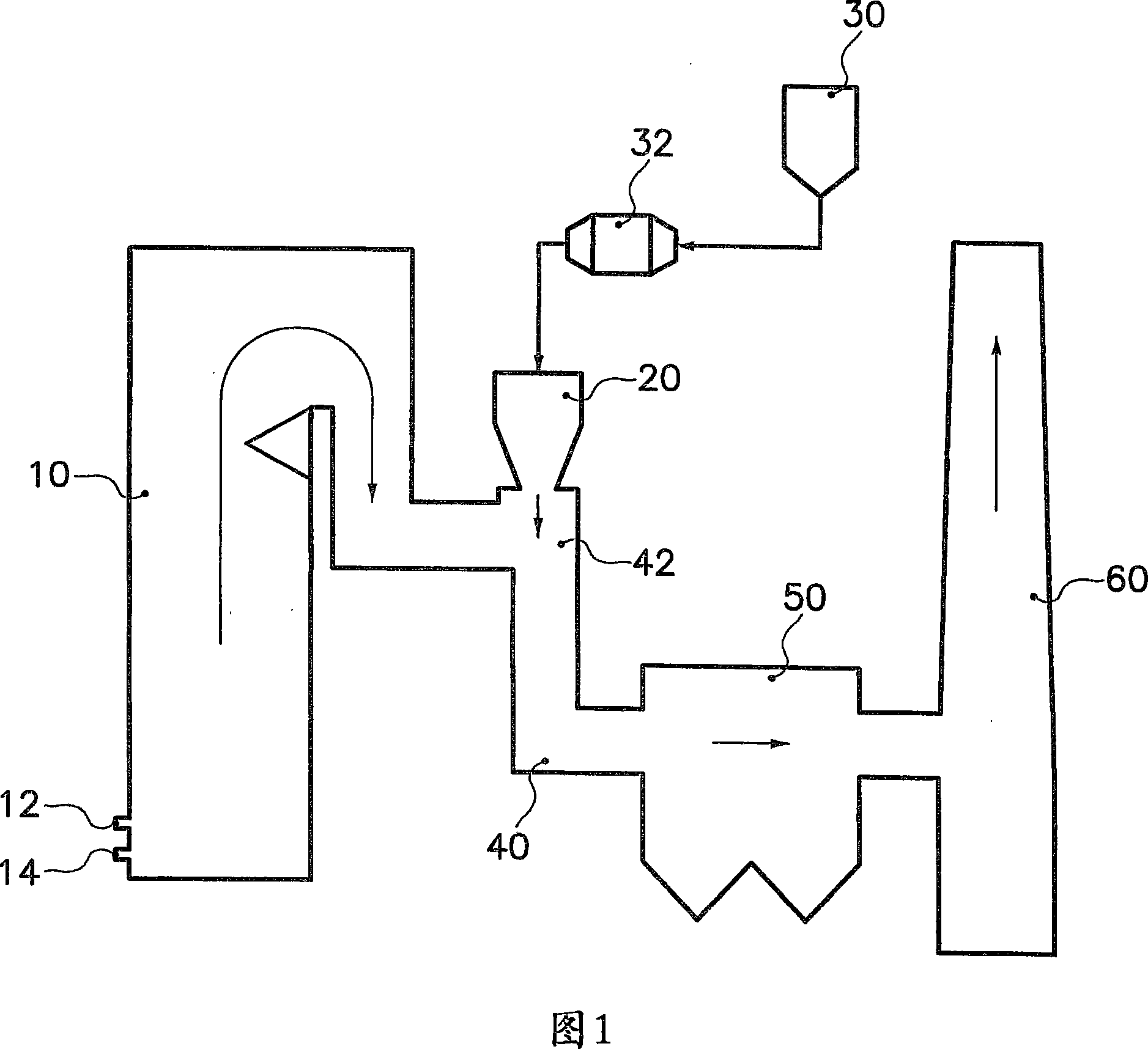
Image

Examples
Embodiment 1
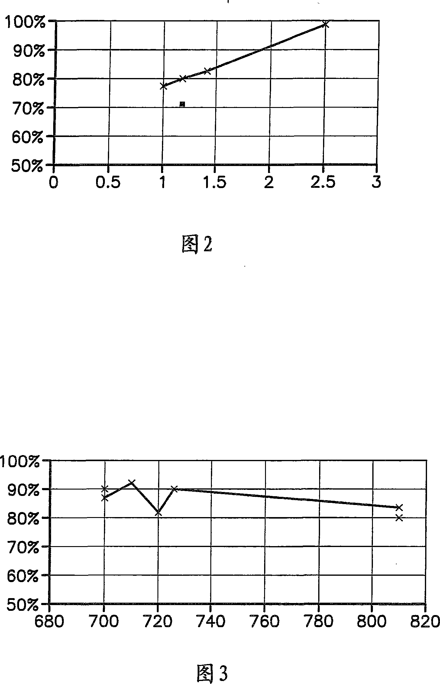
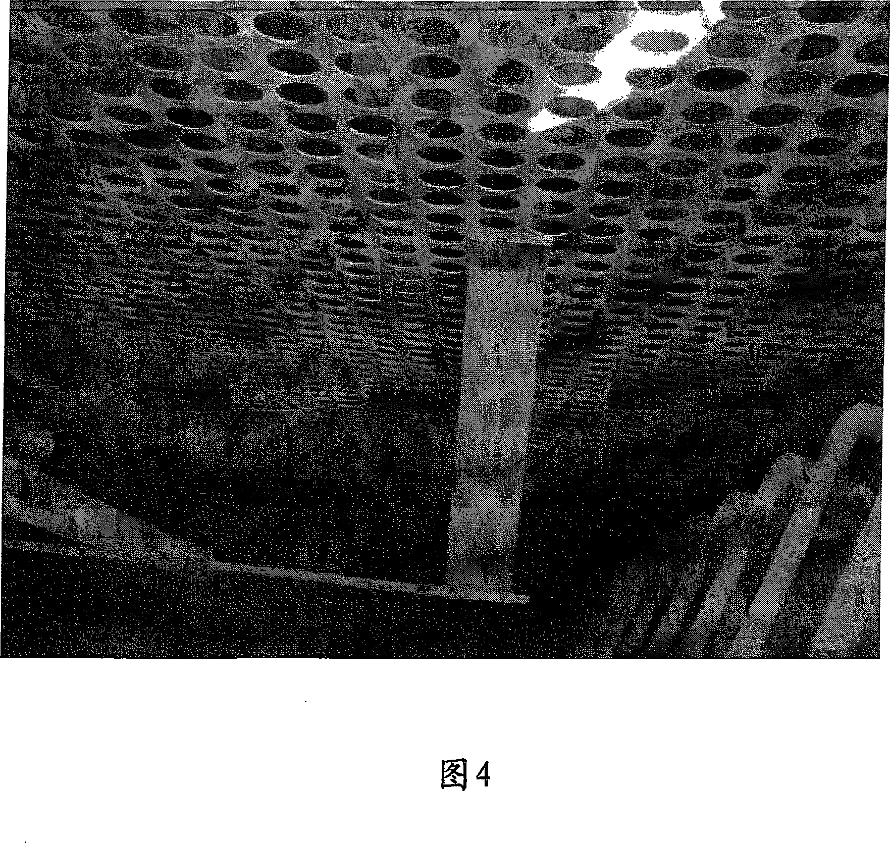
[0032] Trona was injected into the flue gas at a temperature of 750F at NSR values of 1.0, 1.2 and 1.4. Figure 2 shows SO as a function of the normalized stoichiometric ratio (NSR) of trona 2 Remove %. From these experiments it can be seen that trona gives about 80% SO at an NSR of 1.2 2 removal rate. Figure 4 shows SO 2 Removal of the perforated plate of the ESP in the glassworks after the system was operated with trona for five months. It can be seen that the panel is relatively free of solids buildup.
Embodiment 2
[0034] As a comparative example, sodium bicarbonate was sprayed under the same conditions as in Example 1 at an NSR of 1.2. The result is shown in Figure 2. 72% SO 2 % SO removal significantly lower than trona at the same temperature and NSR 2 Remove %. Figure 5 shows the operation of SO using sodium bicarbonate 2 Remove the perforated plate of the ESP in the glasshouse after the system. It can be seen that the panel has significant solids buildup.
Embodiment 3
[0036] Trona was injected into the flue gas at a temperature of 750°F to 805°F at an NSR of 1.5. Figure 3 shows SO as a function of flue gas temperature 2 Remove %. From these experiments it can be seen that trona yields up to 91% SO 2 removal rate and is effective over a broad high temperature range.
[0037] From the above experiments it can be seen that the removal of SO from flue gas streams at high temperature 2 Sometimes trona is more effective than sodium bicarbonate. Thus, the system can use less absorbent material than a sodium bicarbonate system to achieve the same sulfur reduction. Furthermore, it can be seen that Trona has good performance over a broad high temperature range. Finally, compared to the system using sodium bicarbonate, SO using trona 2 The removal system has much less solids buildup in the perforated plates of the ESP.
PUM
 Abstract
Description
Claims
Application Information