Technique for preparing hydrogen gas by hydrocarbons gases

A gas preparation and hydrocarbon gas technology, applied in hydrogen, chemical recovery, inorganic chemistry, etc., to achieve the effect of solving catalyst consumption and deactivation

Inactive Publication Date: 2008-08-27
INST OF PROCESS ENG CHINESE ACAD OF SCI
View PDF0 Cites 26 Cited by
  • Summary
  • Abstract
  • Description
  • Claims
  • Application Information

AI Technical Summary

Problems solved by technology

In the hydrogen production process of the present invention, in addition to obtaining no CO or CO 2 In addition to the high-purity hydrogen, because the catalyst is recycled, there is no problem of catalyst consumption, and there is no problem of system instability due to its deactivation.

Method used


Image

  • Technique for preparing hydrogen gas by hydrocarbons gases
  • Technique for preparing hydrogen gas by hydrocarbons gases

Examples


Embodiment 1

[0035] Using methane gas as raw material, the flow rate is 220ml / min;

[0036] Ni / Al 2 o 3 As a catalyst, the metal loading is 10-35%wt;

[0037] Three-stage fixed-bed cracking reactor with a temperature of 500°C;

[0038] The heat exchange unit after cracking adopts shell and tube heat exchanger;

[0039] No gas-solid separation equipment after cracking;

[0040] No hydrogen purification equipment;

[0041] The post-combustion heat exchange unit adopts a shell-and-tube heat exchanger;

[0042] The gas-solid separation equipment after combustion adopts cyclone separator;

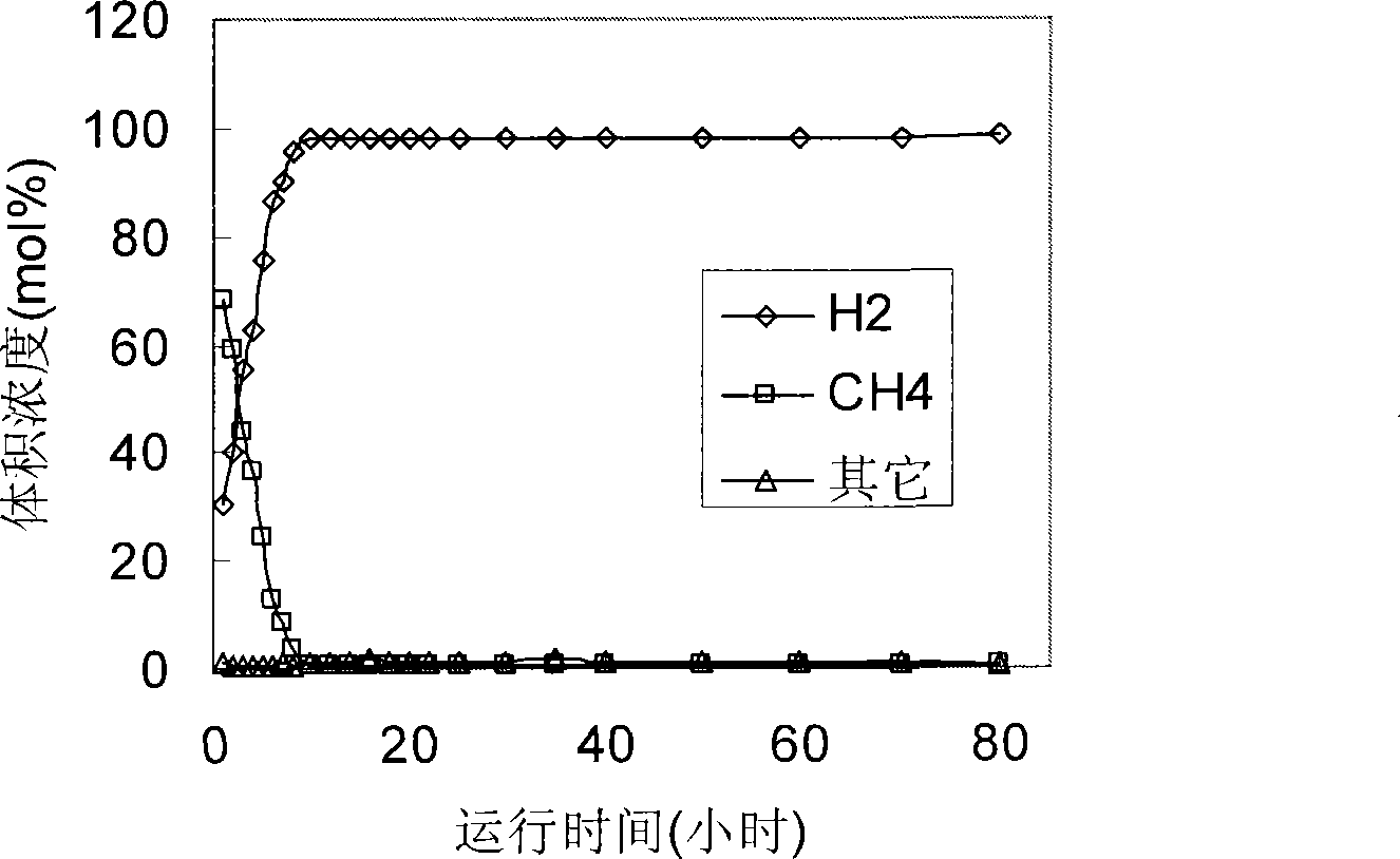
[0043] Experiment runs 80 hours, product gas composition and content measure with gas chromatography (AgilentN9608), the situation that the composition of product gas changes with time is as follows figure 1 As shown, it can be seen that once the system runs stably, the product gas composition is stable and the impurity content is very low.

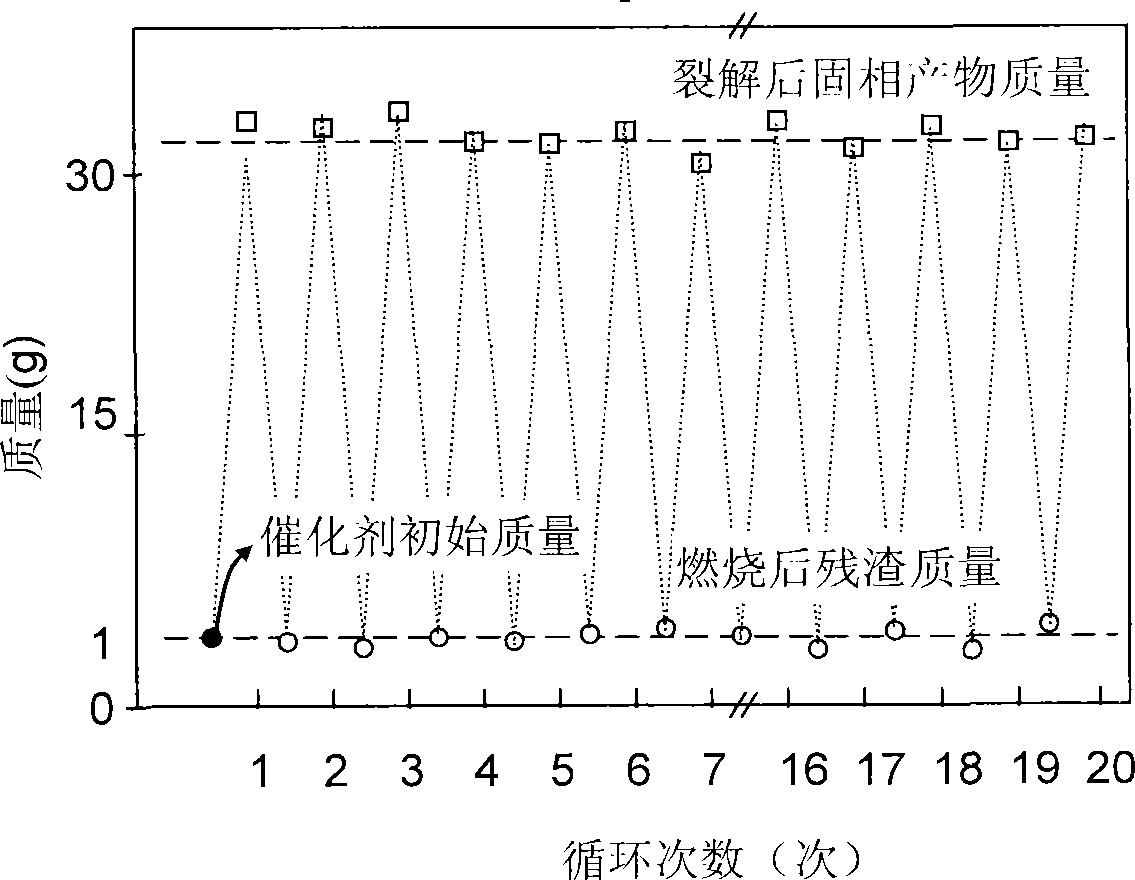
[0044] In order to verify the change of catalyst activity ...

Embodiment 2

[0047] The mixed gas of methane and hydrogen is used as the raw material, the flow rate is 350ml / min, and the volume content of hydrogen is 10%;

[0048] Fe / MgO is the catalyst, and the metal loading is 5-25%wt;

[0049] Three-stage fixed-bed pyrolysis reactor with a temperature of 650°C;

[0050] The heat exchange unit after cracking adopts shell and tube heat exchanger;

[0051] No gas-solid separation equipment after cracking;

[0052] No hydrogen purification equipment;

[0053] The post-combustion heat exchange unit adopts a shell-and-tube heat exchanger;

[0054] The gas-solid separation equipment after combustion adopts cyclone separator;

[0055] The experiment was run for 80 hours, and the gas chromatographic detection results were averaged after the stable operation, and the hydrogen-rich gas component obtained was H 2 : 99.6%, CH 4 : 0.2%, other 0.2%; no CO 2 Or CO is detected.

Embodiment 3

[0057] Using liquefied petroleum gas as raw material, the flow rate is 280ml / min;

[0058] Co / MgO is the catalyst, and the metal loading is 5-30%wt;

[0059] Three-stage fixed-bed pyrolysis reactor with a temperature of 660°C;

[0060] The heat exchange unit after cracking adopts shell and tube heat exchanger;

[0061] No gas-solid separation equipment after cracking;

[0062] No hydrogen purification equipment;

[0063] The post-combustion heat exchange unit adopts a shell-and-tube heat exchanger;

[0064] The gas-solid separation equipment after combustion adopts cyclone separator;

[0065] The experiment was run for 80 hours, and the gas chromatographic detection results were averaged after the stable operation, and the hydrogen-rich gas component obtained was H 2 : 99.2%, CH 4 : 0.1%, other 0.7%; no CO 2 Or CO is detected.


PUM


Abstract

The invention relates to a process for preparing hydrogen by hydrocarbon gases, which cracks the hydrocarbon gas to hydrogen and carbon/catalyst composite material by means of catalysis. The hydrogen is the product, and solid products are used as fuel to provide energy for the cracking process. Burned residue is recycled and cycled to be catalyst in the process of preparing the hydrogen. In the process of preparing the hydrogen of the invention, besides, the hydrogen with high purity and without CO and CO2 can be obtained, the catalyst is not consumed due to the recycling use of the catalyst, and problems that the catalyst losing activity results in an unstable system and the like are not existed.

Description

technical field [0001] The invention belongs to the field of energy and chemical industry, and in particular relates to a process for preparing hydrogen from hydrocarbon gas. Background technique [0002] As a clean energy that is increasingly valued by people, hydrogen energy is an important way to use hydrogen fuel cells for high-efficiency energy conversion, but in actual use, hydrogen with high purity is required to meet the requirements of hydrogen fuel cells. Hydrogen is always combined with other elements in nature. Therefore, how to economically and effectively separate hydrogen from natural compounds (such as water, coal, natural gas, etc.) is the key to hydrogen production technology. [0003] The current mature steam reforming technology refers to the reaction of fossil fuels and water vapor at a certain temperature and pressure. Taking the steam-methane reforming hydrogen production process widely distributed in nature as a raw material as an example, the result...

Claims


Application Information

Patent Timeline
Patent Type & Authority Applications(China)
IPC IPC(8): C01B3/26
CPCY02P20/584
Inventor 田亚峻陈运法
Owner INST OF PROCESS ENG CHINESE ACAD OF SCI
Why Eureka
Try Eureka