Both-end water-generating immersed hollow fiber film component

A fiber membrane and submerged technology, applied in the field of submerged hollow fiber membrane modules, can solve problems such as unreasonable aeration methods, inability to detect and repair, and uneven gas distribution, so as to reduce the frequency of backwashing and chemical cleaning. Easy installation and reduced volume

Active Publication Date: 2008-09-03
TIANJIN MOTIMO MEMBRANE TECH
View PDF0 Cites 15 Cited by
  • Summary
  • Abstract
  • Description
  • Claims
  • Application Information

AI Technical Summary

Problems solved by technology

[0004] 1. Since the support tubes used to support the components are located at the periphery of the components, multiple support tubes are required and the structure is complex
Moreover, the support pipe only has the function of support and has a single function
[0005] 2. The existing submerged column membrane module produces water at one end, the utilization rate of the membrane filament is reduced, and the water production is low
[0006] 3. Due to the unreasonable aeration method and uneven gas distribution, the local impact of the membrane filament is large, the membrane filament is prone to damage, and the service life is reduced
[0007] 4. Complex engineering installation
For the curtain membrane module, there are problems that cannot be detected and repaired during use

Method used


Image

  • Both-end water-generating immersed hollow fiber film component
  • Both-end water-generating immersed hollow fiber film component
  • Both-end water-generating immersed hollow fiber film component

Examples


Embodiment Construction

[0020] The present invention will be described in detail below in conjunction with the accompanying drawings and specific embodiments.

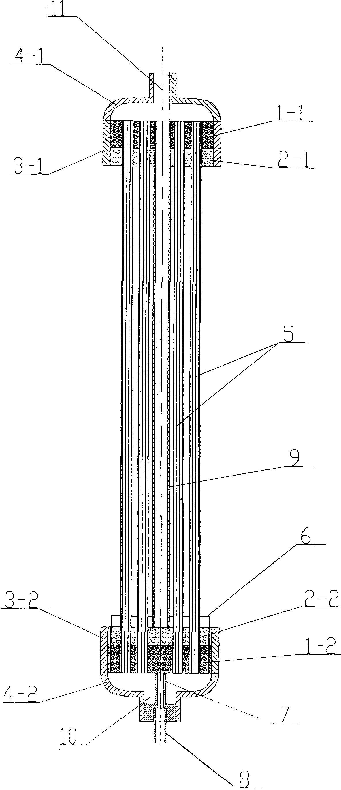
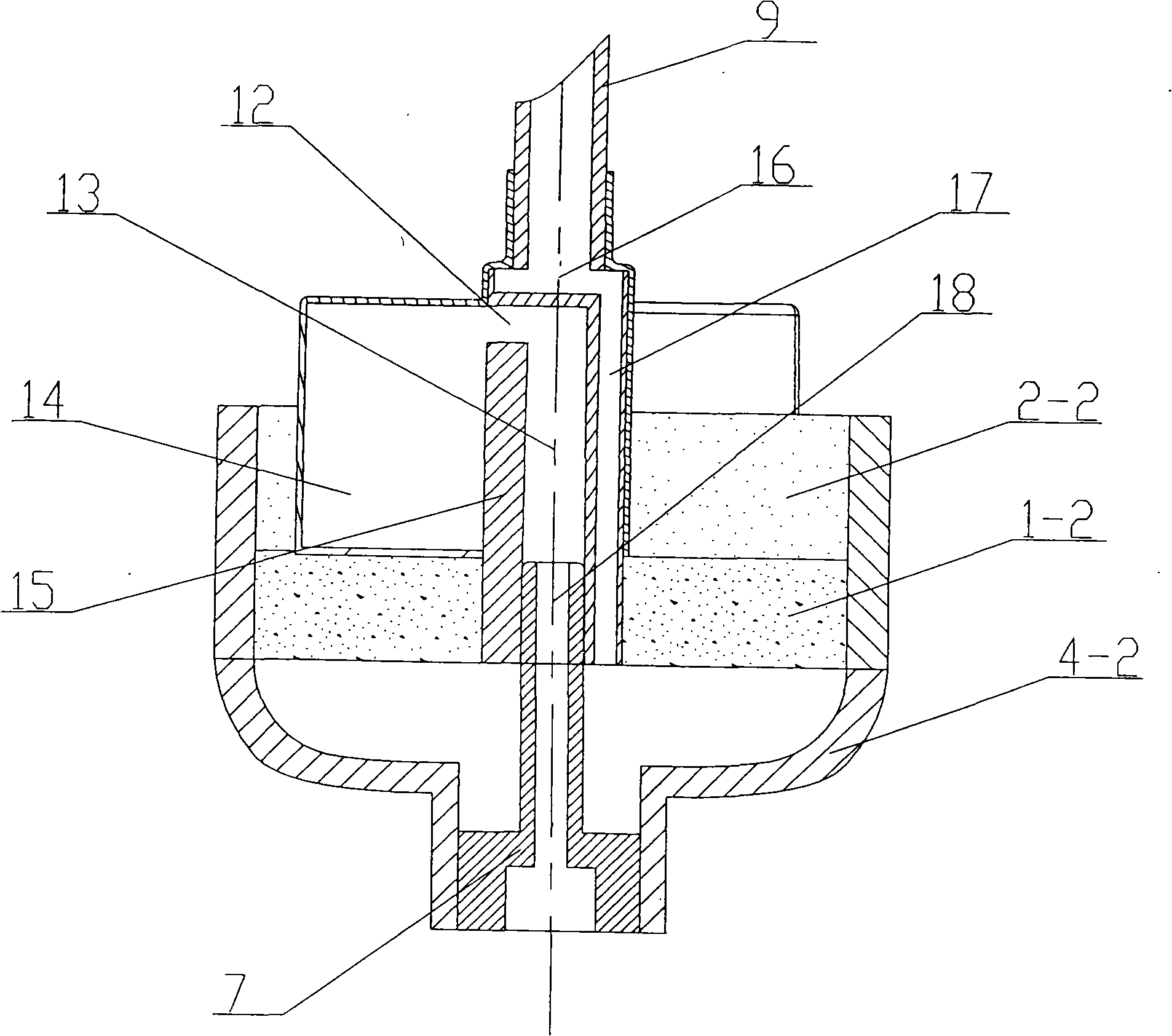
[0021] The schematic diagram of the double-end water production submerged hollow fiber membrane module of the present invention is as follows figure 1 As shown, a plurality of hollow fiber membranes 5 are fixed by two sealing layers poured in the screw barrels 3-1, 3-2. In order to improve the service life of the membranes, the sealing layers are made of epoxy resin sealing layers 1-1, 1 -2 and polyurethane sealing layer 2-1, 2-2. Because the polyurethane sealing layer is relatively soft, it is beneficial to protect the film filaments. The screw barrel 3-1 is connected with the screw cover 4-1, the screw barrel 3-2 is connected with the screw cover 4-2, and the hollow part of each hollow fiber membrane is opened on both ends of the sealing layer. An air inlet 10 is provided on the screw cover 4-2, and a water outlet 11 is provided on the sc...


PUM


Abstract

The invention discloses a hollow fibrous membrane module, the two ends of which can have water flowing out for immersing, and aims to provide a membrane module, of which the support tube not only has support function, but also serves as a water channel with the two ends having water flowing out, the structure is simple and the aeration is even. An aeration inlet column is arranged at an air inlet, one end of the aeration inlet column communicates with an aeration device, and the other end is spliced with an inlet pipe. The aeration device comprises an aeration body, in which an air collecting chamber and a water collecting chamber are arranged, the outer side of the aeration body is connected with a plurality of sealed air chambers, and a plurality of aeration holes are arranged on each sealed air chamber. The water collecting chamber is internally provided with a plurality of water outlets, the lower end of the aeration body is provided with a plurality of water inlets, and water passages communicating the water inlets with the water outlets are arranged on the aeration body. One end of the support tube is opened on the end surface of the sealing layer of the water outlet end, and the other end communicates with the water collecting chamber of the aeration device. The support tube has the support function and serves as the water channel with the two ends having water flowing out, thereby simplifying the structure of the membrane module, reducing the volume of the membrane core, reducing the construction cost, and improving the utilization ratio and the water yield of membrane threads.

Description

technical field [0001] The invention relates to a water treatment device, in particular to a submerged hollow fiber membrane module. Background technique [0002] As a method of wastewater treatment, hollow fiber membranes have been more and more widely used in the water treatment industry. Among them, the membrane filter element is soaked in the activated sludge tank, and the activated sludge and treated water are filtered. Membrane separation activated sludge method for solid-liquid separation. This method has the advantages of reducing the volume of the activated sludge tank, or shortening the reaction time in the activated sludge tank, eliminating the need for a final sedimentation tank, and reducing the floor area of ​​the treatment facility. It can be filtered, so it can also reduce the management of activated sludge. Because of so many advantages, it has become popular in recent years. [0003] Due to the deficiencies of the existing submerged hollow fiber membrane ...

Claims


Application Information

Patent Timeline
Patent Type & Authority Applications(China)
IPC IPC(8): B01D63/02C02F1/44C02F3/12
CPCY02W10/10
Inventor 刘建立苗蕾于鸿来安强王海涛吴静宇
Owner TIANJIN MOTIMO MEMBRANE TECH
Why Eureka
Try Eureka