Vibrating magnetic coupling fluid bed flue gas desulfurization reactor

A fluidized bed and reactor technology, applied in the field of fluidized bed flue gas desulfurization reactor, can solve the problems of slow desulfurization reaction speed, easy fouling of reactor, low efficiency, etc., and achieve fast desulfurization reaction speed and increase flow rate The effect of high operating range and high reaction efficiency

Inactive Publication Date: 2008-09-10
HARBIN INST OF TECH
View PDF1 Cites 14 Cited by
  • Summary
  • Abstract
  • Description
  • Claims
  • Application Information

AI Technical Summary

Problems solved by technology

[0004] The object of the present invention is to provide a vibration-magnetic coupling fluidized bed flue gas desulfurization reactor, which can solve the problems encountered by existing magnetic fluidized bed flue gas desulfurization

Method used


Image

  • Vibrating magnetic coupling fluid bed flue gas desulfurization reactor
  • Vibrating magnetic coupling fluid bed flue gas desulfurization reactor
  • Vibrating magnetic coupling fluid bed flue gas desulfurization reactor

Examples


specific Embodiment approach 1

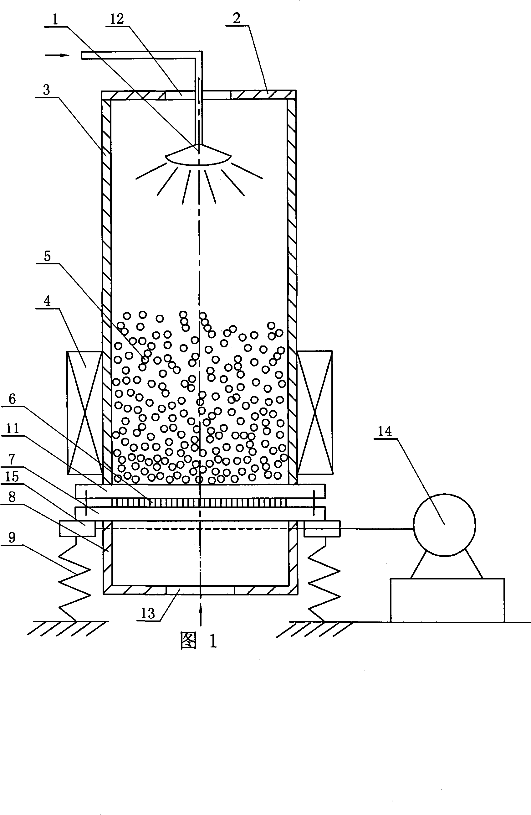
[0008] Specific Embodiment 1: This embodiment is described with reference to FIGS. 1 to 3. The flue gas desulfurization reactor of this embodiment includes a fluidized bed, an atomizing nozzle 1, a magnetic coil 4, and a bellows 8; the fluidized bed consists of The cylinder body 3, the annular upper cover 2, the air distribution plate 6, the upper fixed frame plate 11, the lower fixed frame plate 7, and the magnetic bed material 5; The central hole of the cover 2 is the flue gas outlet 12. The upper fixed frame plate 11 and the lower fixed frame plate 7 are stacked together and fixed between the lower end surface of the cylinder body 3 and the upper end surface of the bellows 8. The cylinder body 3 A magnetic bed material 5 is installed inside, the air distribution plate 6 is fixed between the upper fixed frame plate 11 and the lower fixed frame plate 7, a flue gas inlet 13 is provided under the bellows 8, and the atomizing nozzle 1 passes through the annular upper cover The c...

specific Embodiment approach 2

[0009] Specific Embodiment 2: This embodiment is described in conjunction with Fig. 1 to Fig. 3. The cylinder body 3, the annular upper cover 2, the air distribution plate 6, the upper fixed frame plate 11, and the lower fixed frame plate 7 of this embodiment are all made of non-magnetic materials. Made, conducive to the smooth reaction of desulfurization. Other components and connections are the same as those in the first embodiment.

specific Embodiment approach 3

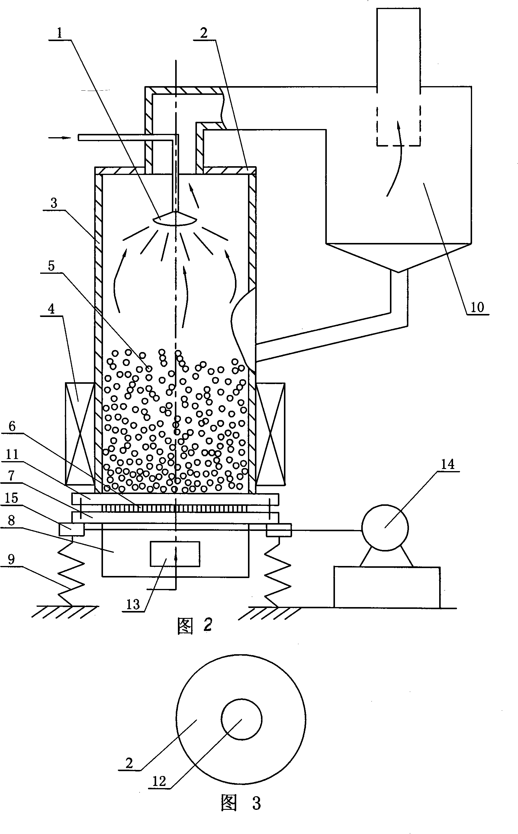
[0010] Specific Embodiment 3: This embodiment is described with reference to FIG. 1 and FIG. 2 . The flue gas inlet 13 of this embodiment is arranged on the bottom plate of the wind box 8 or on the side wall of the wind box 8 , as required. Other components and connections are the same as those in the first embodiment.

[0011] The working principle is: sulfur-containing flue gas enters the reactor filled with magnetic powder through the air distribution plate 6, and the desulfurizer enters the reactor from above the fluidized bed through the atomizing nozzle. The desulfurizing agent droplets react chemically with SOx in the rising flue gas, and the unreacted desulfurizing agent falls and covers the magnetic particles, forming a desulfurizing agent reaction layer to continue to react with SOx. When the gas velocity or amplitude is large, the magnetic particles and desulfurizer are carried out of the reactor by the flue gas, enter the separation device 10 with the flue gas (see...


PUM


Abstract

A magnetic vibration coupling fluidized bed flue gas desulfurization reactor relates to a fluidized bed flue gas desulfurization reactor which aims at the problems of slow speed, short time and low efficiency of desulfurization reaction of a magnetic fluidized bed flue gas desulfurization device. An annular upper cover (2) is fixedly connected with the upper end surface of a cylinder (3); the central hole of the annular upper cover (2) is a flue gas outlet (12); an upper fixing frame board and a lower fixing frame board are fixedly arranged between the cylinder (3) and a bellows (8); a magnetic bed material (5) is arranged in the cylinder (3); a grid plate (6) is fixedly arranged between the upper and the lower fixing frame boards; an atomizer (1) is hung in the cylinder (3); a magnetic spiral loop (4) is sheathed on the cylinder (3); the two ends of three to four excitation springs (9) are respectively and fixedly connected with bases (15) and the ground; the bases (15)are fixedly connected with the lower fixing frame board (7); three or four bases are all connected with an excitation motor (14). The reactor of the invention has the advantages of fast speed, long time, high efficiency of desulfurization reaction and little scale formed on the inner wall of the reactor.

Description

technical field [0001] The invention relates to a fluidized bed flue gas desulfurization reactor, which belongs to the technical field of environmental protection equipment. Background technique [0002] Coal dominates China's energy resources. The coal-based energy structure will be difficult to change for a long time to come. The relatively backward coal production and consumption methods have increased the pressure on environmental protection. Coal consumption is the main cause of soot-type air pollution and the main source of greenhouse gas emissions. Coal-fired flue gas desulfurization is a basic technical countermeasure to protect the atmospheric environment and control the harm of acid rain caused by sulfur dioxide. In particular, domestic thermal power plants, whose coal consumption accounts for more than 42% of the national coal output, are in urgent need of mature flue gas desulfurization technology with independent intellectual property rights and suitable for ...

Claims


Application Information

Patent Timeline
IPC IPC(8): B01D53/83B01D53/50
Inventor 李响王淑彦郝振华刘国栋陆慧林刘文铁何玉荣
Owner HARBIN INST OF TECH
Why Eureka
Try Eureka