Method and device for reclaiming residual heat emitted by aluminum electrolysis bath

The technology of an aluminum electrolytic cell and a recovery method, which is applied in the field of waste heat recovery and its device from an aluminum electrolytic cell, can solve the problems of low waste heat utilization rate, energy utilization rate of less than 50%, and high cost, and achieve high waste heat recovery efficiency and structure Simple, low-cost effect

Inactive Publication Date: 2008-09-10
NORTHEASTERN UNIV +1
View PDF0 Cites 8 Cited by
  • Summary
  • Abstract
  • Description
  • Claims
  • Application Information

AI Technical Summary

Problems solved by technology

In fact, aluminum electrolysis needs to consume a lot of electric energy, but its energy utilization rate is less than 50%, that is to say, 50% of the energy is dissipated and lost. Recycling and utilizing this part of energy is an urgent problem to be solved by the aluminum electrolysis industry.
The cost of this technology is relatively high, and the utilization rate of waste heat is relatively low (the electric energy generated per ton of aluminum is 200 kWh, and only two-sevenths of the total heat dissipation is recovered)

Method used


Image

  • Method and device for reclaiming residual heat emitted by aluminum electrolysis bath
  • Method and device for reclaiming residual heat emitted by aluminum electrolysis bath
  • Method and device for reclaiming residual heat emitted by aluminum electrolysis bath

Examples


example 1

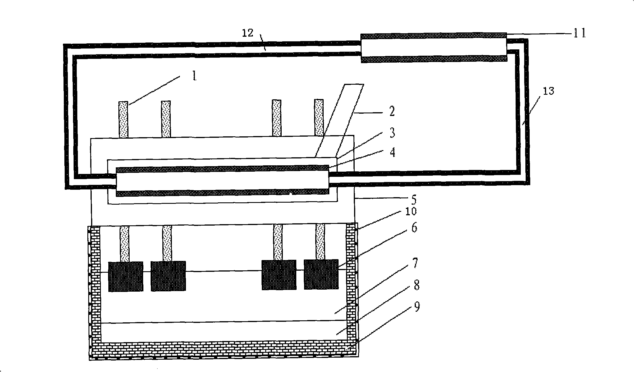
[0019] Example 1: The recovery device for distributing waste heat of the aluminum electrolytic cell of the present invention is as attached figure 1 , figure 2 As shown, a first heat exchange tube with fins is installed in the flue gas channel in the web box on the electrolytic cell, a second heat exchange tube is installed on the side wall of the electrolytic cell, the first heat exchange tube and the second heat exchange tube The outlets of the second heat exchange tubes are respectively connected to the inlets of the tubular condensers of the condensing system through the gas transmission pipelines, and the outlets of the condensers are respectively connected to the inlets of the first heat exchange tubes and the second heat exchange tubes through the return pipes, forming two circulation systems.

[0020] The present invention is implemented on a 300KA electrolyzer, and the heat exchange medium loaded in the first heat exchange tube and the second heat exchange tube is et...

example 2

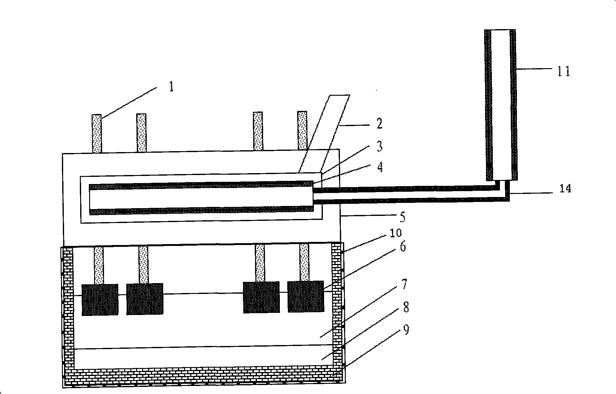
[0021] Example 2: The composition of the device is as follows image 3 , Figure 4 As shown, when the reflux of the heat exchange medium condensate adopts the gross suction method, stainless steel wire mesh is installed in the first heat exchange tube, the second heat exchange tube, the gas pipeline, the return pipeline and the tube wall of the condenser. The gas transmission pipeline and the return pipeline connected between the first heat exchange tube, the second heat exchange tube and the condenser are respectively combined into one gas transmission or return pipeline. The second heat exchange tube is installed on the steel plate on the side wall of the aluminum electrolytic cell.

[0022] The recovery method is the same as Example 1, except that the heat exchange medium is acetone. When the heat exchange medium is heated and vaporized in the first heat exchange tube and the second heat exchange tube, it enters the condenser through the middle of the combined gas transmi...

example 3

[0023] Example 3: The composition of the experimental device used and the recovery method are the same as in Example 2, except that the heat exchange medium is methanol.

[0024] The second heat exchange tube is installed on the steel plate of the side shell of the aluminum electrolytic cell. The recovery of waste heat from the upper part of the electrolytic tank reaches 65%, and the recovery of waste heat from the wall of the electrolytic tank reaches 58%.


PUM


Abstract

The invention relates to a method and a device thereof for recycling waste heat dissipated from an aluminum cell. The device is formed by that: a first heat exchange pipe which is arranged inside a flue on the upper part of the aluminum cell and on the lower part of a gas collecting system and a second heat exchange pipe which is arranged on the outer shell of the electrolytic cell wall are connected with a condensing system through gas pipes; an outlet of the condensing system is connected with inlets of the first heat exchange pipe and the second heat exchange pipe through return passages. The method comprises the following steps that: the first heat exchange pipe and the second heat exchange pipe are heated by the waste heat generated during the process of aluminum electrolysis of the aluminum cell, and heat exchange media in the heat exchange pipes are gasified and flow to the condensing system; after condensation and recycling of released heat, and heat exchange medium liquid after condensation returns to the first heat exchange pipe and the second heat exchange pipe and then performs reciprocating cycle operation. The method and the device thereof for recycling the waste heat dissipated from the aluminum cell is characterized in that: the structure of the device is simple; the manufacturing cost is low; the heat exchange media can perform cycle operation; the operation cost is low; the waste heat recycling rate is high and can reach 60 percent of the total heat dissipating capacity of the aluminum cell.

Description

technical field [0001] The invention relates to a method and a device for recovering waste heat emitted by an aluminum electrolytic cell in an electrolytic aluminum process. Background technique [0002] Whether it is non-ferrous metallurgy or ferrous metallurgy, the metallurgical industry is a large energy-consuming industry, and there are a lot of energy-saving problems. The coke oven blast furnace and steelmaking process of iron and steel enterprises have a considerable amount of waste heat that has not been recycled (waste heat temperature as high as 1600 ° C), and the waste heat of aluminum electrolytic cells in the aluminum electrolysis industry has not yet been recycled. At present, the aluminum electrolysis industry has been using the traditional Hall-Heroult method. The electrolyte used is a cryolite-alumina molten salt system. The carbon anode and carbon cathode are placed up and down. When the current passes through the molten electrolyte, a large amount of resis...

Claims


Application Information

Patent Timeline
Patent Type & Authority Applications(China)
IPC IPC(8): C25C3/06
Inventor 王兆文吕定雄石忠宁马成贵吴有威高炳亮班允刚马绍先于亚鑫戚喜全王超
Owner NORTHEASTERN UNIV
Why Eureka
Try Eureka