
Strain transducer based on porous microstructure optical fibre

A microstructure optical fiber and strain sensor technology, applied in the field of sensing, can solve the problems of difficult control of the melting taper process, high price of photonic crystal fibers, etc., and achieve the effects of being conducive to popularization and application, low price and high sensitivity

Inactive Publication Date: 2008-09-10
SHANGHAI INST OF OPTICS & FINE MECHANICS CHINESE ACAD OF SCI
View PDF0 Cites 29 Cited by
  • Summary
  • Abstract
  • Description
  • Claims
  • Application Information

AI Technical Summary

Problems solved by technology

However, the photonic crystal fiber used in it is more expensive, and its fusion tapering process is more difficult to control

Method used


Image

  • Strain transducer based on porous microstructure optical fibre
  • Strain transducer based on porous microstructure optical fibre
  • Strain transducer based on porous microstructure optical fibre

Examples


Embodiment 2

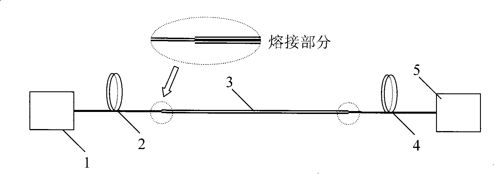
[0032] Example 2 as Figure 5 As shown, the porous microstructure optical fiber 3 is fixed on the surface of the component 6 with an adhesive. When a force perpendicular to the direction of the fiber is applied, the member 6 will generate bending strain, while the porous microstructured optical fiber 3 maintains the same deflection as the member 6 . The strain of the porous microstructure optical fiber 3 includes both tensile strain and bending and shearing strain. The tensile strain will cause the translation of the transmission spectrum, and the bending and shearing strain will cause the shape of the transmission spectrum to change. As in Example 1, using the single longitudinal mode or multi-longitudinal mode light source 1, the deflection of the optical fiber 3 can be derived by measuring and deriving the change of the received optical power of the single-mode optical fiber 4, and thus the bending strain of the component 6 can be obtained.

Embodiment 3

[0033] Example 3 as Figure 6 As shown, the center of the cylindrical member 9 has a through hole running through the entire length, through which the porous microstructure optical fiber 3 passes and is fixed therein. When the cylindrical member 9 is subjected to torque, a torsional strain will be generated, and the porous microstructure optical fiber 3 maintains the same torsional strain as the cylindrical member 9, and the torsional strain will cause changes in the shape of the transmission spectrum of the device. As in Examples 1 and 2, using a single longitudinal mode or multi-longitudinal mode light source 1, the torsional strain of the porous microstructured optical fiber 3 can be inverted by measuring and deriving the change of the received optical power of the single-mode optical fiber 4, and the cylindrical Torsional strain of member 9.


PUM


Abstract

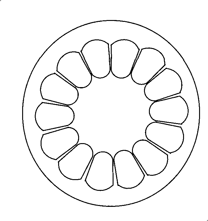
The invention provides a strain sensor based on porous micro-structure optical fibre, which is characterized in that the strain sensor is composed of a light source, a lead-in single-mode optical fibre, a porous micro-structure optical fibre, a lead-out single-mode optical fibre and a photoelectric detector, which are connected in series and sequence. The porous micro-structure optical fibre is a pure silica core which is enwound by a ring of sector air holes; the edges of the core present ratchet wheel shaped structure. The strain sensor can measure tension strain, flexibility strain and torsion strain, and has the advantages of high sensitiveness, high temperature resistance and electromagnetic radiation resistance.

Description

technical field [0001] The invention belongs to the sensing technology, and is a strain sensor based on a porous microstructure optical fiber, which can be applied to static and dynamic radial, axial, torsion, bending strain and stress sensing. Background technique [0002] Due to its strong anti-electromagnetic interference ability, high sensitivity, good electrical insulation, safety and reliability, corrosion resistance, and many advantages such as the ability to form an optical fiber sensor network, fiber optic sensors are widely used in various fields such as industry, agriculture, biomedicine, and national defense. prospect. [0003] There are currently several technical solutions for fiber optic strain sensors, including Fiber Bragg Grating (FBG for short), Long Period Grating (LPG for short), Mach-Zehnder Interferometer (Mach-Zehnder Interferometer, Referred to as MZ-I) and optical fiber Sagnac ring, etc., although their structures are different, they are actually b...

Claims


Application Information

Patent Timeline
Patent Type & Authority Applications(China)
IPC IPC(8): G01B11/16G01L1/24G01D5/353G02B6/02G02B6/255
Inventor 王允韬蔡海文耿健新瞿荣辉方祖捷
Owner SHANGHAI INST OF OPTICS & FINE MECHANICS CHINESE ACAD OF SCI
Learn More