Combined interference device for aspheric surface measurement

A measuring device and aspheric technology, which is applied in the direction of measuring devices, optical devices, instruments, etc., can solve the problems of difficult to change fringe frequency, difficult to realize real-time dynamic measurement, and impossible to measure aspheric surface.

Inactive Publication Date: 2008-09-24
HUNAN UNIV
View PDF0 Cites 38 Cited by
  • Summary
  • Abstract
  • Description
  • Claims
  • Application Information

AI Technical Summary

Problems solved by technology

However, in the transverse shearing interference, the interference area between the original wave surface and the shearing wave surface does not cover the entire pupil surface, and the measured aspheric surface cannot be completely measured, and the results of transverse shearing interferometry in two orthogonal directions are required to recover Raw wave surface, image processing is very troublesome
At the same time, in this technology, the phase shift is driven by piezoelectric ceramics (PZT), and the measurement process requires strict vibration isolation, so it is impossible to achieve measurement in ordinary environments, and it is also difficult to achieve real-time dynamic measurement
[0008] The sixth prior art (referring to P.Hariharan et al., Measurement of aspheric surface using a micro

Method used


Image

  • Combined interference device for aspheric surface measurement
  • Combined interference device for aspheric surface measurement
  • Combined interference device for aspheric surface measurement

Examples


Embodiment Construction

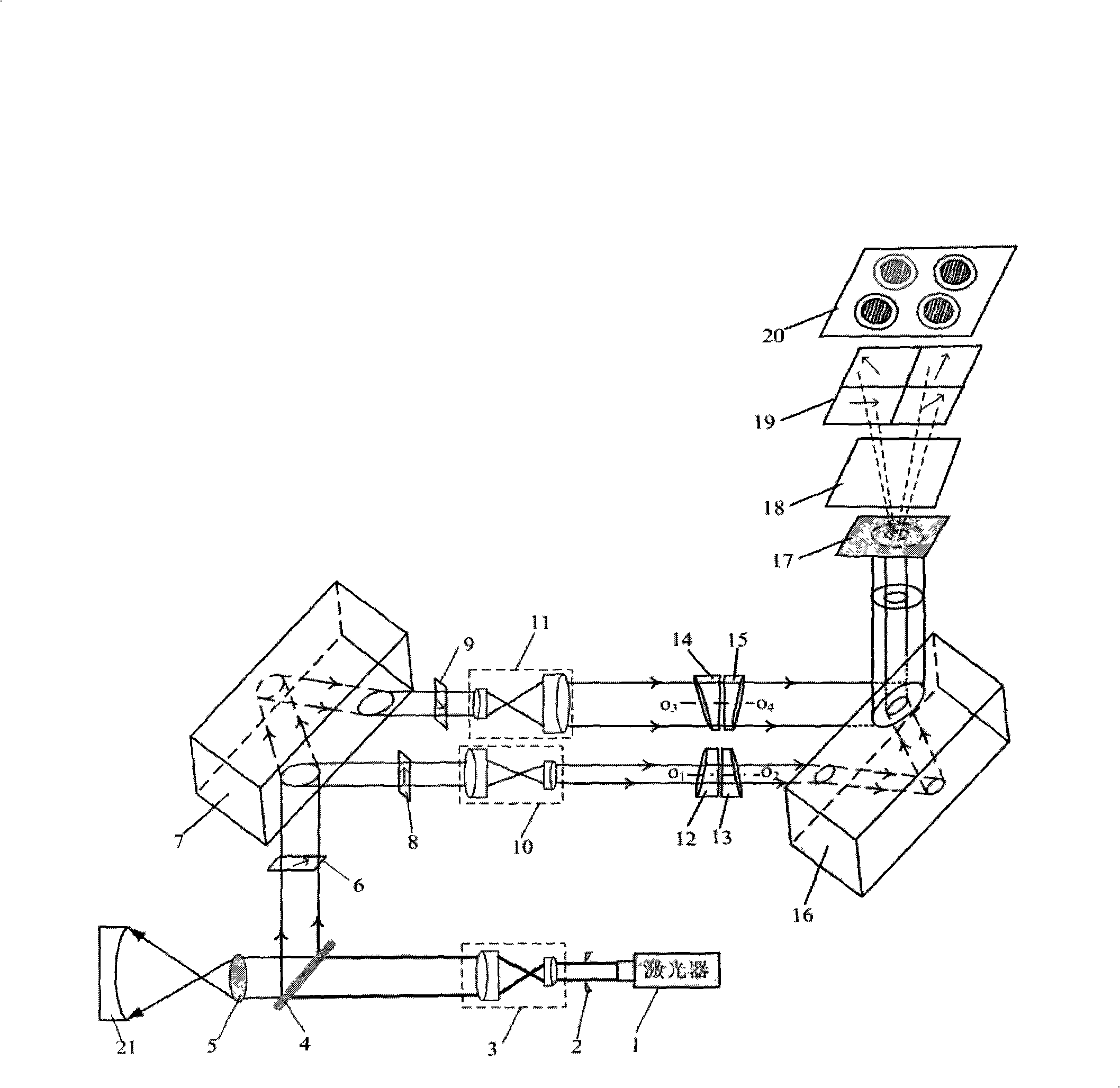
[0043] Such as figure 1 As shown, the combined interference device for measuring aspheric surface shape of the present invention has a laser 1, and a spatial filter 2, a beam expander system 3, a beam splitter 4, a conversion lens 5, The measured aspheric mirror 21; the laser light reaches the measured aspheric surface 21 and is reflected back by the measured aspheric surface 21, and is incident on the beam splitter 4 through the conversion lens 5 again and is reflected by the beam splitter 4, after being reflected by the beam splitter 4 The first vertical optical path is formed, and the 45° polarizer 6 and the first optical flat plate 7 are successively placed on the vertical optical path. After the laser passes through the first optical flat plate 7, two horizontal optical paths are formed. The vertical polarizer 8, the beam shrinker system 10, the first optical wedge 12, and the second optical wedge 13 are arranged in order; the horizontal polarizer 9, the beam expander sys...


PUM


Abstract

A combined interference device for measurement of aspheric surface includes a laser, a spatial filter, two beam expanding systems, a beam shrinking system, a spectroscope, a convertible lens, three polarizers, two optical plates, four circular optical wedges with small wedge angle, a beam-dividing grating, a 1/4 wave plate, a polarizer group and a CCD. In the device, real-time measurement is realized through simultaneous phase-shifting method, and frequency conversion function is realized through rotating two pairs of double optical wedges. The experimental device adopts common optical elements, so the cost is low, and the device can measure aspheric surfaces of different diameters and is suitable for the plane and the sphere. The real-time high precision measurement in conventional environment can be realized, and the invention has frequency conversion function, which is very effective for treating the mirror surface with discontinuous regions.

Description

technical field [0001] The invention is a combined interferometer integrating radial shearing, fast frequency conversion and synchronous phase shifting, and is mainly used for three-dimensional measurement of aspheric surface shape. Background technique [0002] The use of aspheric optical system can eliminate spherical aberration, coma, astigmatism, field curvature, and reduce light energy loss, so as to obtain high-quality image effects and high-quality optical characteristics, and can be widely used in various modern optoelectronic products, images Dealing with products such as digital cameras, VCD, DVD, computers, CCD camera lenses, large-screen projection TVs and military, astronomical and medical industries. In the processing and experimentation of aspheric optical elements, the precise measurement of their surface shape is crucial; And ultra-precision machining is difficult to achieve. In recent years, people have proposed many aspheric surface measurement technolog...

Claims


Application Information

Patent Timeline
IPC IPC(8): G01B11/24
Inventor 朱勇建尹韶辉范玉峰吕冰海
Owner HUNAN UNIV
Why Eureka
Try Eureka