Film separated activated sludge apparatus

An activated sludge and membrane separation technology, applied in water/sludge/sewage treatment, biological water/sewage treatment, osmosis/dialysis water/sewage treatment, etc., can solve the problem of low BOD volume load, reduce sludge production rate, Unable to achieve high flux and other problems, to achieve the effect of preventing water quality deterioration and delaying clogging

Inactive Publication Date: 2008-10-01
ASAHI KASEI CHEM CORP
View PDF2 Cites 11 Cited by
  • Summary
  • Abstract
  • Description
  • Claims
  • Application Information

AI Technical Summary

Problems solved by technology

For example, in Patent Document 1, the life of the membrane under high BOD volume load is improved by adjusting the temperature of the aeration tank, but high flux cannot be achieved
In addition, in Patent Document 2, the sludge production rate was reduced by adjusting the pH of the membrane separation tank, but the BOD volume load was still very low

Method used


Image

  • Film separated activated sludge apparatus
  • Film separated activated sludge apparatus
  • Film separated activated sludge apparatus

Examples


Embodiment 1

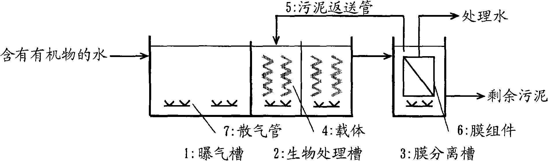
[0099] The membrane separation activated sludge device used in this embodiment is shown in figure 1 . The aeration tank 1 (capacity 12L), the biological treatment tank 2 (capacity 12L), and the membrane separation tank 3 (capacity 4L) were connected in series in the direction from upstream to downstream of the flow of water containing organic matter. Aeration pipes 7 are respectively provided in each tank to allow aeration. The biological treatment tank 2 is equally divided into two stages, and fixed-bed carriers are arranged in the two stages. The fixed bed type carrier adopts a spiral shape with a length of 60 cm and an outer diameter of 8 cm made by making a polyvinylidene chloride fiber into a ring shape with a length of 1.5 cm, and fixing a part of it on a copper core material wrapped in plastic. carrier.

[0100] A membrane module (hollow fiber membrane made of PVDF, 0.1 μm in pore size, 0.035 m in membrane surface area) is installed in the membrane separation tank 3 ...

Embodiment 2

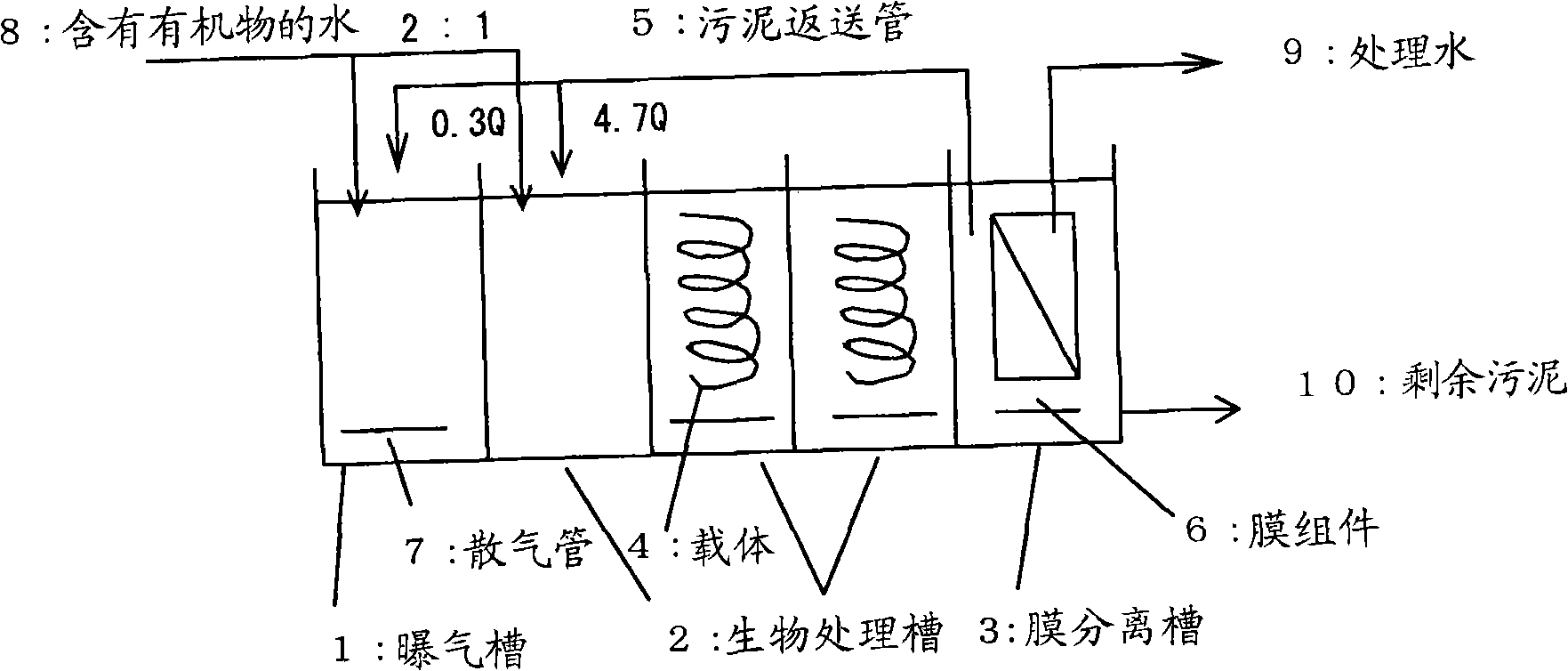
[0104] The membrane separation activated sludge device used in this embodiment is shown in figure 2 . Aeration tank 1 (capacity 2m 3 ), biological treatment tank 2 (capacity 6m 3 = 2m 3 ×3 tanks) and membrane separation tank 3 (capacity 2m 3 ) are connected in series along the upstream to downstream direction of the flow of water containing organic matter. Biological treatment tank 2 is divided into 3 levels. In the upper stage, the flow is carried out by propeller agitation without aeration. The middle stage and the lower stage are respectively provided with diffuser pipes 7 for aeration, and respectively provided with fixed-bed carriers 4 . The fixed bed carrier 4 adopts a helix with a length of 1.8 m and an outer diameter of 8 cm made by making a polyvinylidene chloride fiber into a ring shape with a length of 1.5 cm, and fixing a part of it on a copper core material wrapped in plastic. shape carrier. Two sets of membrane modules (hollow fiber membranes made of PVD...

Embodiment 3

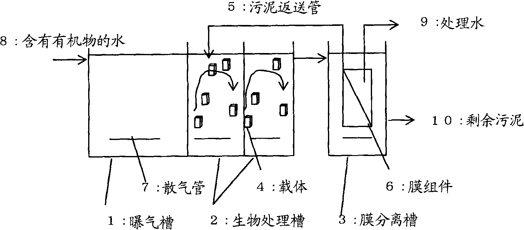
[0108] Using the same device as in Example 1, the carrier 4 in the biological treatment tank 2 was replaced with a flow carrier. A summary of the device is shown in Figure 4 . As the mobile carrier 4, a soft polyurethane sponge 7 mm square carrier "Bio-colony" (BIO-colony) for water treatment microorganisms manufactured by Achilles Co., Ltd. was used. After acclimatization, the volumetric load of BOD is kept constant at 1.5kg / m per day after inputting a fluid carrier with a volume ratio of 20% to the biological treatment tank 2 3 , keep the flux constant at 0.7m per day 3 / m 2 , The membrane module was continuously operated without backwashing or membrane cleaning, and the differential pressure between the membranes (TMP) was measured.

[0109] After 45 days, TMP increased by 7kPa, and the membrane fouling rate (daily TMP increase) was 0.66kPa per day, which was low enough for practical use. The sludge production rate was calculated from the amount of excess sludge disch...


PUM

PropertyMeasurementUnit
surface areaaaaaaaaaaa

Abstract

The invention provides a membrane separation activated sludge device and processing method. The device and method can process with high BOD volume load. Even if the device operates with high flux, the device can defer block of the membrane so as to reduce frequency of washing membrane and changing membrane and to prevent addition of water quality deterioration of processing water and sludge. The membrane separation activated sludge device is used for processing water containing organism having an aeration tank, a biological processing tank and a membrane separation tank configured in series along an upriver direction toward a downriver direction. The biological processing tank has a carrier. In addition, the device further has a returning element that returns the sledge in the membrane separation tank to the biological processing tank.

Description

technical field [0001] The present invention relates to a membrane separation activated sludge device for treating water containing organic matter, and a method for treating water containing organic matter with the membrane separation activated sludge device. Background technique [0002] Membrane separation activated sludge plants are often used to treat water containing organic matter. Since the device can obtain clear treated water with low concentration of suspended matter (SS: Suspended solids), and can increase the sludge concentration (MLSS: Mixed LiquorSuspended Solids) from 2000 to 5000 mg / L in the previous activated sludge method to 5000~30000mg / L, therefore, the processing capacity per unit volume of the processing tank can be improved. [0003] However, since the separation membrane used in the membrane separation activated sludge device is expensive, and the membrane needs to be washed or replaced periodically, there is a problem of high operating costs. In or...

Claims


Application Information

Patent Timeline
Patent Type & Authority Applications(China)
IPC IPC(8): C02F3/12C02F1/44
CPCY02W10/10
Inventor 清水正古田喜丈
Owner ASAHI KASEI CHEM CORP
Why Eureka
Try Eureka