Device and method for eliminating fluorinated gases
A gas, fluorination technology, applied in chemical instruments and methods, separation methods, plasma and other directions, can solve problems such as paralysis and hinder the smooth progress of semiconductor engineering equipment
- Summary
- Abstract
- Description
- Claims
- Application Information
AI Technical Summary
Problems solved by technology
Method used
Image
Examples
Embodiment 1
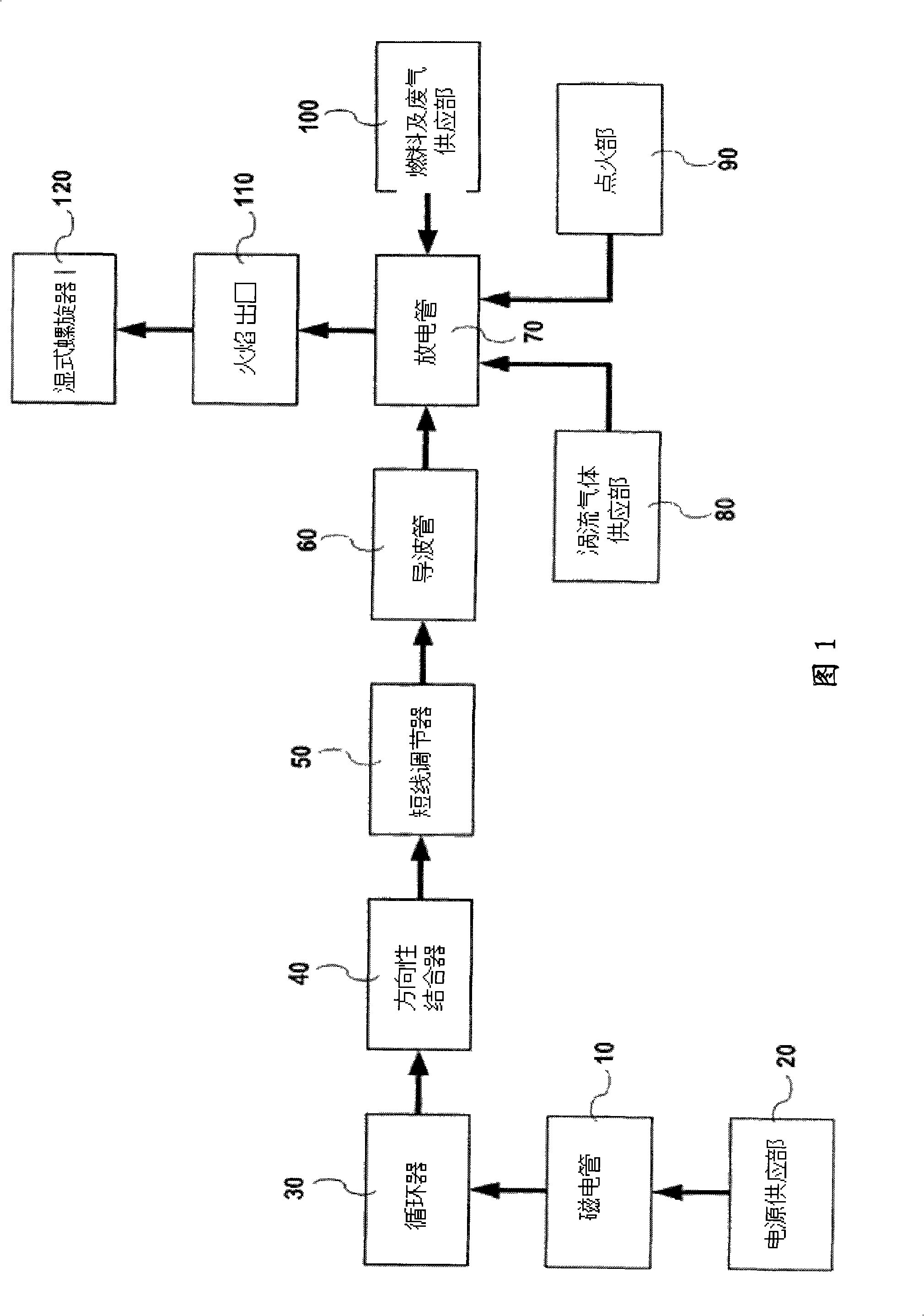
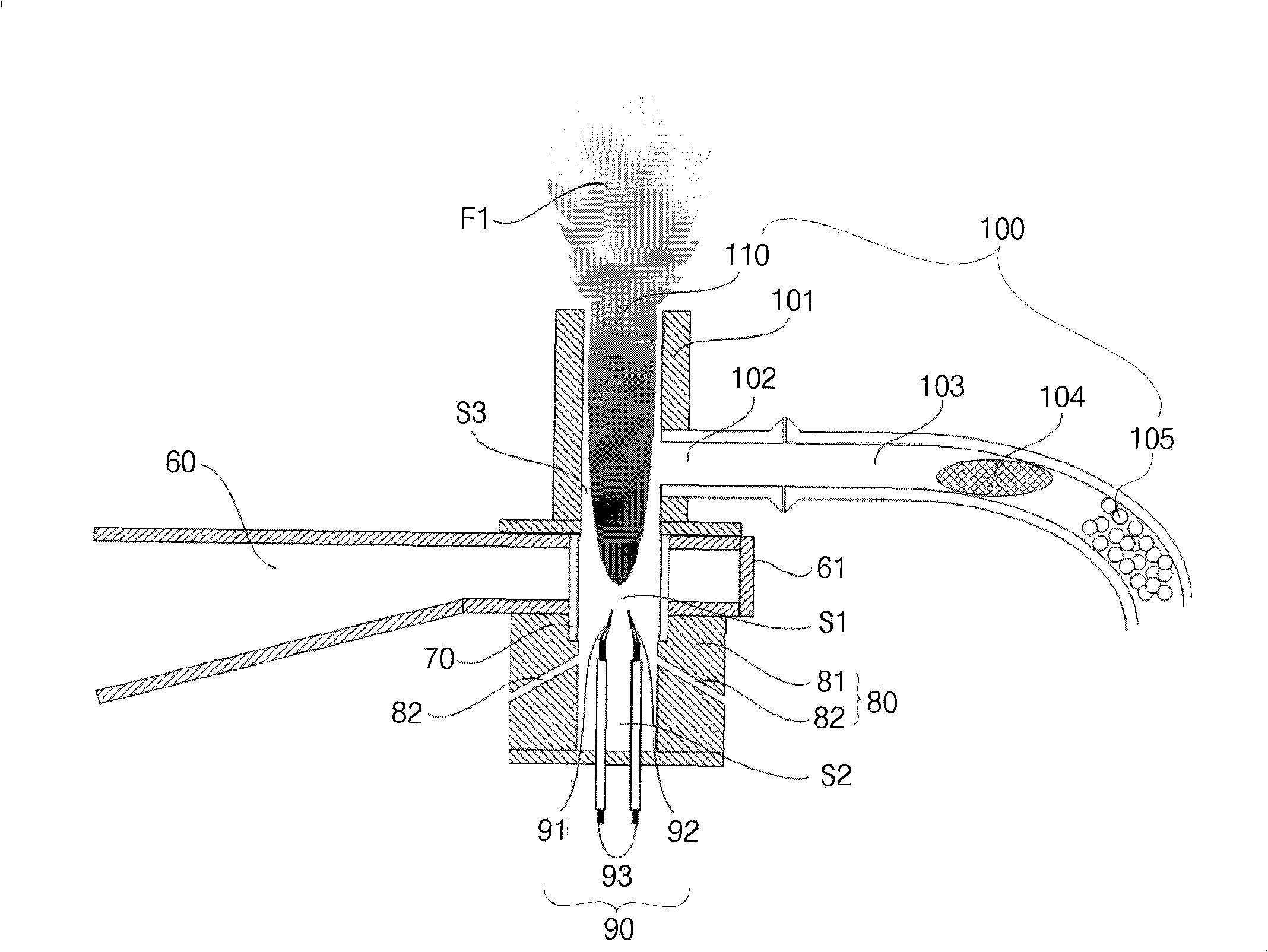
[0062] Figure 6 and Figure 7 It uses an infrared tube analyzer (FTIR) to measure nitrogen trifluoride (NF) before and after passing through a high-temperature plasma flame. 3 ) analysis results chart. The device used is as figure 2 device with the structure shown.
[0063] In the embodiment, air containing NF3 is injected by a blower, compressed air is used for swirl gas, and methane is used for injecting fuel.
[0064] At this time, the flow rate of injected air and compressed air is 500 liters per minute and 50 liters per minute, methane is 15 liters per minute, NF 3 600 ml per minute. by NF 3 After the polluted gas passes through the high-temperature plasma flame in the discharge tube, the remaining NF remaining in the exhaust gas is measured by an infrared spectrophotometer. 3 According to the quantitative results, it can be known that under the above-mentioned implementation conditions, more than 99% are decomposed by the high-temperature plasma flame.
Embodiment 2
[0066] Figure 8 and Figure 9 It uses an infrared tube analyzer (FTIR) to measure the sulfur hexafluoride (SF) before and after passing through a high-temperature plasma flame. 6 ) analysis results chart. The device used is as figure 2 device with the structure shown.
[0067] In this example the injection gas is SF 6 , Nitrogen and oxygen are mixed and injected with a gas mixing device, compressed air is used for swirl gas, and methane is used for fuel. At this time, the injected nitrogen and oxygen and compressed air flows are 120 liters and 30 liters per minute, SF 6 100 ml per minute. By SF 6 After the polluted gas passes through the high-temperature plasma flame in the discharge tube, the SF remaining in the exhaust gas is measured by an infrared spectrometer 6 Quantitative results, it can be known that under the above factual conditions, more than 99% are decomposed by high temperature plasma flame
[0068] Figure 10 Shown is a graph of decomposition efficien...
Embodiment 3
[0071] Figure 11 and Figure 12 It uses an infrared tube analyzer (FTIR) to measure nitrogen tetrafluoride (CF) before and after passing through a high-temperature plasma flame. 4) analysis results chart. The device used is as figure 2 device with the structure shown.
[0072] In this example the injected gas is CF 4 , Nitrogen and oxygen are mixed and injected with a gas mixing device, compressed air is used for swirl gas, and methane is used for fuel. At this time, the injected nitrogen and oxygen and compressed air flows are 40 liters and 30 liters per minute, CF 4 50 ml per minute are infused. by CF 4 After the polluted gas passes through the high-temperature plasma flame generated in the discharge tube, the amount of CF4 remaining in the exhaust gas is measured by an infrared spectrometer. It can be known that under the above-mentioned factual conditions, more than 98% of it is destroyed by the high-temperature plasma flame. break down
[0073] Figure 13 Shown...
PUM
 Abstract
Description
Claims
Application Information
 - R&D
- Intellectual Property
- Life Sciences
- Materials
- Tech Scout
- Unparalleled Data Quality
- Higher Quality Content
- 60% Fewer Hallucinations
Browse by: Latest US Patents, China's latest patents, Technical Efficacy Thesaurus, Application Domain, Technology Topic, Popular Technical Reports.
© 2025 PatSnap. All rights reserved.Legal|Privacy policy|Modern Slavery Act Transparency Statement|Sitemap|About US| Contact US: help@patsnap.com


