Construction method of relief well

A construction method and a technology of relief wells, which are applied in infrastructure engineering, coastline protection, construction, etc., can solve problems such as poor product quality, low construction efficiency, and restrictions on relief wells, so as to achieve less time-consuming hole formation and higher manufacturing efficiency. Hole quality, effect of reducing workload

Active Publication Date: 2010-06-09
GUANGDONG CONSTR ENG GRP +1
View PDF3 Cites 0 Cited by
  • Summary
  • Abstract
  • Description
  • Claims
  • Application Information

AI Technical Summary

Problems solved by technology

Due to the limitations of the pore-making method itself, the construction efficiency is low, the well washing time is long, and the product quality is poor. After the well is formed, the water output is often insufficient or there is no water at all, which leads to the consequence of the failure of the relief well, which is seriously restricted. This ensures the normal function of relief wells, a mature protection facility for dikes and dams.

Method used


Image

  • Construction method of relief well
  • Construction method of relief well
  • Construction method of relief well

Examples


Embodiment 1

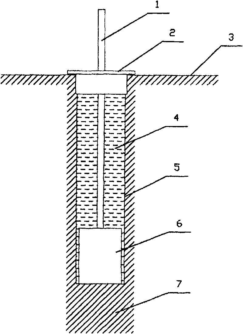
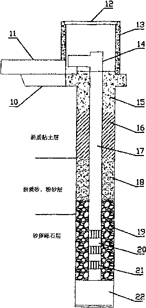
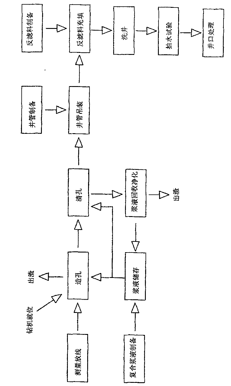
[0045] refer to figure 1 , figure 2 and image 3 , figure 1 It is a schematic diagram of the pore-making principle of the relief well of the present invention, figure 2 Schematic diagram of the relief well structure of the present invention; image 3 It is a flow chart of the relief well construction method of the present invention. The invention proposes a construction method for a relief well, which includes steps such as measuring and setting out, hole making, hole cleaning, well pipe hoisting, reverse filter material filling, well cleaning, pumping test, wellhead treatment, and superstructure construction. in:

[0046] In the hole-making process, the direct earth-borrowing drilling rig is used to make the hole and the high polymer composite slurry is used to protect the hole. In the hole cleaning process, the high polymer composite slurry is used to clean the hole.

[0047] The pore-making process includes the preparation and storage of polymer composite slurry. Du...

Embodiment 2

[0060] The method of operation is the same as in Example 1, except that the high polymer composite slurry used in the present example has a composition weight ratio of:

[0061] water 1000;

[0062] Bentonite 100;

[0063] PAM 10;

[0064] CMC+PAC10;

[0065] Industrial alkali 1.5

[0066] weighting agent 3;

[0067] fluid loss reducer 1;

[0068] The above components are prepared in proportion, and put into the swirl type pulping machine successively to make a slurry. The proportion of the prepared new slurry is controlled at 1.14-1.15, and the viscosity is controlled at about 23s. The high polymer composite slurry of this embodiment It is used for the construction of relief wells whose geological characteristics are mainly silt layer, plastic silt layer, and thin pebble layer. The results are:

[0069] Mud skin thickness test (stand still for 12h) 1.8mm. It took 3.1 hours to make a hole at a depth of 24m, 1 hour to clean the hole, and 7.5 hours to wash the well. The ...

Embodiment 3

[0071] The method of operation is the same as in Example 1, except that the high polymer composite slurry used in the present example has a composition weight ratio of:

[0072] water 1000;

[0073] Bentonite 80;

[0074] PAM 22;

[0075] CMC 13;

[0076] Industrial alkali 0;

[0077] weighting agent 8;

[0078] fluid loss reducer 0;

[0079] The above components are prepared in proportion, and put into the swirl type pulping machine successively to make a slurry. The density of the prepared new slurry is controlled at 1.13-1.14, and the viscosity is controlled at about 25s. The polymer composite slurry of this embodiment It is used for the construction of relief wells whose geological characteristics are thick pebble layer, silt layer, and the rest are plastic silt soil layers. The results are:

[0080] Mud skin thickness test (stand for 12h) 1.9mm. It took 4.5 hours to build a hole at a depth of 24m, 1.5 hours to clean the hole, and 9 hours to wash the well. The wate...


PUM


Abstract

The invention relates to the engineering technique for protecting a river dyke, in particular to a method for constructing a relief well, comprising the steps of: hole creating, hole cleaning, borepipe making and hoisting, filter material making and filling, hole flushing, pumping test and well top processing, etc. The method is characterized in that: in the hole creating step, a direct soil-borrowing type drilling machine is used to create holes, and created holes are protected by high polymer composite slurry; in the hole clean step, the high polymer composite slurry is directly used to clean holes, and the hole clean step includes a cyclic process of the recovery, the purification, the storage and the reutilization. The high polymer composite slurry is prepared by following components in portion by weight: 1000 portions of water, 70 to 130 portions of bentonite, 5 to 25 portions of polyacrylamide, 2 to 15 portions of cellulose ether, 0 to 9 portions of weight additive, 0 to 5 portions of industrial alkali and 0 to 3 portions of fluid loss additive, and the mixture is stirred into slurry by a swirling flow type pulping machine. The method has the advantages of easy and quick operation, high production efficiency, good product quality and long service life; moreover, in the process of construction, the method has the advantages of energy and water conservation, low cost, low noise and no pollution.

Description

technical field [0001] The invention relates to a construction method of a relief well in river dam protection engineering. Background technique [0002] The relief well is a common and effective protection and reinforcement facility for river embankments, and its main function is to dredge the underground seepage in the embankment during the flood season. When the water level of the outer river rises, the pressure relief well acts as a drainage and decompression, thereby reducing the confined water head and seepage pressure acting on the sand layer of the embankment foundation or the covering layer in the dam, and preventing seepage deformation and seepage damage of the embankment. Protect the safety of the embankment. The relief well structure is as figure 1 As shown, the well pipe is usually made of PVC pipe, the upper part is the riser pipe, and the lower part is the water filter pipe. The part of the water filter pipe is excavated on the pipe wall to facilitate water...

Claims


Application Information

Patent Timeline
Patent Type & Authority Patents(China)
IPC IPC(8): E02B3/12E02D19/10
Inventor 陈春光唐捷朗赵资钦唐武兴黄伟瑜刘联伟杨峻杨双泉谢志杰
Owner GUANGDONG CONSTR ENG GRP
Why Eureka
Try Eureka