Preparing method for amorphous alloy stator iron core of high-speed electric machine
An amorphous alloy and stator core technology, which is applied in the manufacture of inductors/transformers/magnets, the manufacture of stator/rotor bodies, circuits, etc., can solve the problems of complex shapes, single non-chips have no rigidity, and complex molding processes, etc. Achieve low operating temperature, environmental protection and easy control, short process time
- Summary
- Abstract
- Description
- Claims
- Application Information
AI Technical Summary
Problems solved by technology
Method used
Image

Examples
Embodiment 1
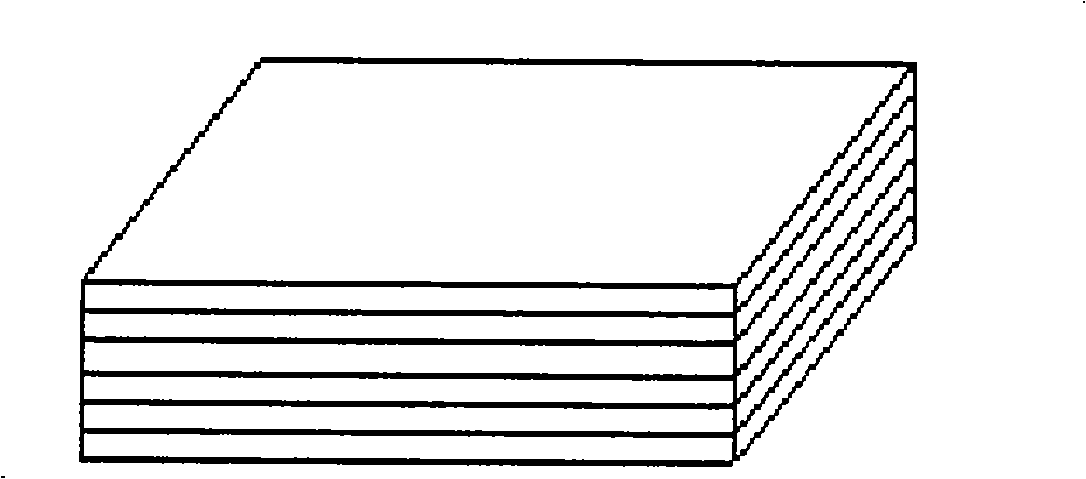
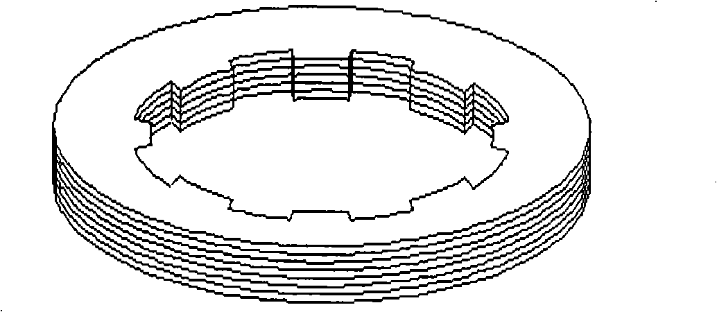
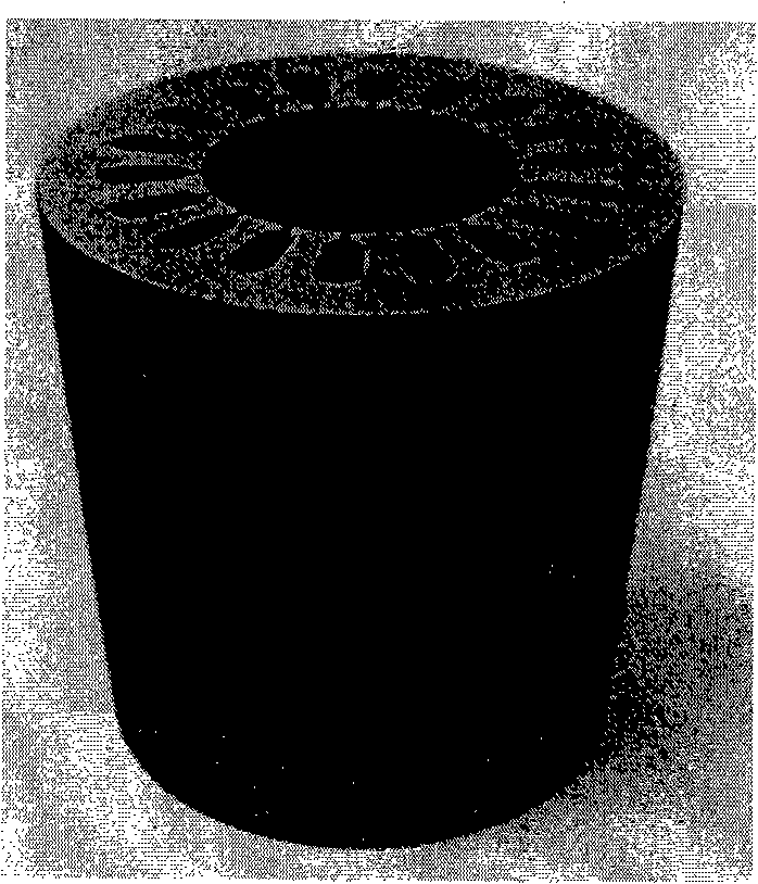
[0040] The Fe-based amorphous alloy strip with nominal composition Fe80Si9B11(at.%) is prepared by planar casting strip method, the strip thickness is 30±1μm, the width is 50mm, and the surface is smooth. First cut the 50mm wide amorphous alloy strip into multiple 110mm long and identically shaped sheets, then stack the amorphous alloy sheets into an amorphous rod with a width of 50mm, a length of 110mm and a height of 66mm, and then place the amorphous rod on the Anneal in a bell-type furnace with nitrogen gas in the bell-type furnace. The annealing process is as follows: 1) heating the amorphous rod to 380° C.; 2) keeping it at about 380° C. for 90 minutes; 3) cooling with the furnace. The annealed amorphous rod was immersed in an impregnating solution with a weight percentage of epoxy resin and acetone of 1:5 for 1 hour, and then kept at 180°C for two hours to solidify. Finally, the amorphous rod was cut into an outer diameter of 45.5 mm by wire cutting. mm, an 18-slot sta...
Embodiment 2
[0048] In order to improve the magnetic induction intensity at the working point of the amorphous stator core, according to the size of the magnetic field heat treatment furnace and the size of the amorphous rod, the following two methods of magnetic field annealing are adopted:
[0049] (1) Magnetic field annealing along the length of the rod
[0050] The schematic diagram of the magnetic field annealing method along the rod length direction is shown in Figure 6 As shown, the amorphous rod is placed in a constant temperature magnetic field heat treatment furnace along the direction in which the length direction and the magnetic field direction are consistent.
[0051] The 50mm wide and 110mm long amorphous wafers obtained by cutting Fe80Si9B11 (at.%) iron-based amorphous alloy strips are stacked into 66mm high amorphous rods, sharing 2375g of amorphous rods, and the amorphous rods are carried out in a nitrogen atmosphere. Annealing, the annealing process is: 1) heating up to ...
PUM
| Property | Measurement | Unit |
|---|---|---|
| Outer diameter | aaaaa | aaaaa |
| The inside diameter of | aaaaa | aaaaa |
| Length | aaaaa | aaaaa |
Abstract
Description
Claims
Application Information
 - R&D
- Intellectual Property
- Life Sciences
- Materials
- Tech Scout
- Unparalleled Data Quality
- Higher Quality Content
- 60% Fewer Hallucinations
Browse by: Latest US Patents, China's latest patents, Technical Efficacy Thesaurus, Application Domain, Technology Topic, Popular Technical Reports.
© 2025 PatSnap. All rights reserved.Legal|Privacy policy|Modern Slavery Act Transparency Statement|Sitemap|About US| Contact US: help@patsnap.com