Six freedom degree jiggle station

A technology of degree of freedom and micro-motion stage, which is applied in the direction of microlithography exposure equipment, large fixed members, metal processing machinery parts, etc., can solve the problem of increasing development cost, prolonging the development cycle, complex assembly and installation process of micro-motion stage drive device, etc. problems, to achieve the effect of short development cycle, simple structure and assembly and installation process

Active Publication Date: 2008-10-22
SHANGHAI MICRO ELECTRONICS EQUIP (GRP) CO LTD
View PDF2 Cites 14 Cited by
  • Summary
  • Abstract
  • Description
  • Claims
  • Application Information

AI Technical Summary

Problems solved by technology

Moreover, the horizontal and vertical micro-actuators have different structural characteristics, and even the driving principles are not the same, which makes the assembly and installation process of the micro-motion stage drive device complicated. For the development of a new type of micro-motion stage, it is necessary to develop two different forms of drivers, which prolongs the development cycle and increases development costs

Method used


Image

  • Six freedom degree jiggle station
  • Six freedom degree jiggle station
  • Six freedom degree jiggle station

Examples


specific Embodiment

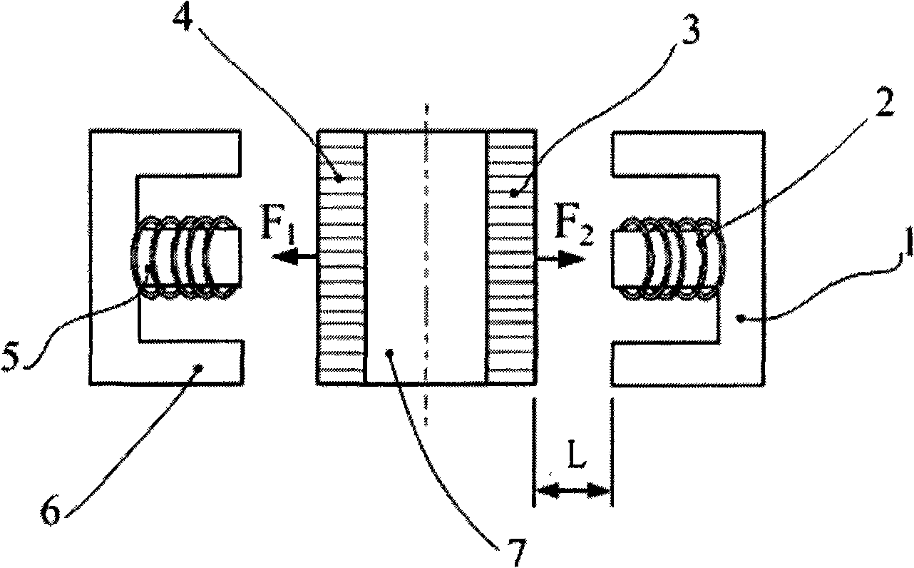
[0015] as attached figure 1 As shown, the present invention adopts the operating principle of the electromagnet, and two groups of electromagnets are placed side by side, and the electromagnet coil is fixedly placed as the stator of the micro-actuator, and the armature part is fixedly installed (mechanically connected or bonded) on the mover of the micro-drive device. superior. When the left and right electromagnet coils 2 and 5 are energized, the electromagnetic attraction acts on the micro-actuator mover 7 through the electromagnetic armatures 3 and 4 respectively, and the position of the mover at which the two electromagnet poles 1 and 6 are equal to the armature attraction is taken as the balance position. By controlling the magnitude of the coil current and fine-tuning the electromagnetic attraction force of the coil poles to the armature, the relative position of the mover 7 of the micro-actuator between the two poles 1 and 6 is controlled, and the functions of rapid pos...

Embodiment 1

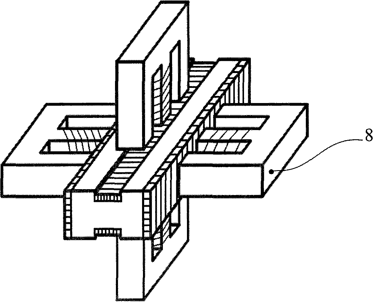
[0047] as attached Figure 4 As shown, the three groups have as figure 2 The micro-actuating device 8 with a special structure is arranged inside the micro-moving table in a circle of 120°, and the geometric center of the three groups of driving devices coincides with the center of gravity of the micro-moving table. The 4 electromagnet coils of the micro-drive device 8 are installed on the large-stroke drive base, and the mover is directly connected with the micro-motion bearing platform. In this way, the interference of the heat generated by the electromagnet coil on the micro-motion stage can be minimized. The position control of the mover can use a capacitive sensor or a nanoscale position sensor such as an LVDT as a measurement sensor.

Embodiment 2

[0049] as attached Figure 5 As shown, it is also possible to use four sets with figure 2 The micro-actuating devices 8 of special structure are vertically arranged inside the micro-moving table, so that the geometric centers of the four groups of the driving devices coincide with the center of gravity of the micro-moving table. This layout method has a redundant degree of freedom in the vertical and horizontal directions, which brings difficulty and complexity to the control, but this method has the advantages of large driving force and smooth movement.

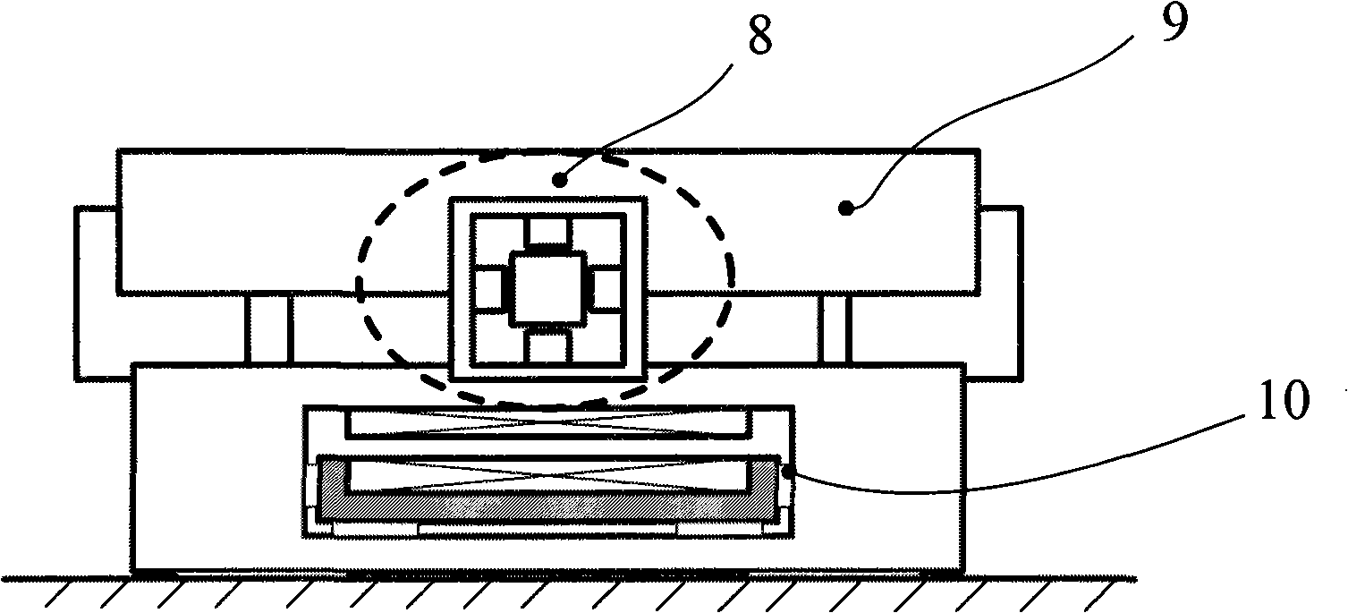
[0050] Such as image 3 As shown, the six-degree-of-freedom micro-motion platform of the present invention also includes a micro-motion bearing platform installation base 9, which is connected to a fixed micro-motion bearing platform; it is also connected with a long-stroke driving device 10, which is used for long-stroke low-precision movement, Realize preliminary rough positioning.


PUM


Abstract

The invention provides a 6-DOF microchecker, which comprises at least three 2-DOF micro-drive apparatuses, wherein, the two 2-DOF micro-drive apparatuses have equal included angles and are horizontally and equally arranged on the circumference of a circular micro-plummer; each 2-DOF micro-drive apparatuses comprise two pairs of electromagnets and a micro-actuator rotor which is provided with an electromagnet armature; as for the two pairs of electromagnets, one pair is horizontally arranged and the other pair is vertically arranged, thereby the two pairs of electromagnets are symmetrically arranged in a cross shape; and the micro-actuator rotor is fixed on the circular micro-plummer and arranged on the center of the cross-shaped electromagnets. 6-DOF micromotion of the mocro-plummer is realized through high-precise control of the electromagnets to the micro-actuator rotor. The 6-DOF microchecker only needs to design a micro-actuator; the structure and the assembly technique of the microchecker are simple; and the development period is short.

Description

technical field [0001] The invention relates to the field of precision micro-control, in particular to a six-degree-of-freedom micro-motion stage. Background technique [0002] Lithography refers to the complex process of sequentially transferring the chip patterns on a series of reticles to the corresponding layers of the silicon wafer through the exposure system. In lithography equipment, the precise positioning of the workpiece table generally adopts the coarse and fine positioning method, and the large-stroke drive The device drives the micro-motion stage to achieve high-speed and high-acceleration long-distance coarse positioning, and the micro-motion stage finally completes the precise positioning. In the lithography machine, the function of the micro-motion table is to carry the silicon wafer and precisely position the silicon wafer. This precise positioning includes vertical and horizontal 6-degree-of-freedom precision adjustment and positioning. The combination of ...

Claims


Application Information

Patent Timeline
Patent Type & Authority Applications(China)
IPC IPC(8): G03F7/20B23Q1/00
Inventor 王天明袁志扬严天宏
Owner SHANGHAI MICRO ELECTRONICS EQUIP (GRP) CO LTD
Why Eureka
Try Eureka