Method for preparing electric vacuum suction element molded by powder injection

A technology of powder injection molding and injection molding, which is applied in the direction of electrical components, electric tube/lamp degassing, circuits, etc. It can solve the problems of high porosity, inability to prepare, and easy powder drop of components, etc., and achieve uniform porosity and uniform control , the effect of high dimensional accuracy

Active Publication Date: 2008-10-22
GRIMAT ENG INST CO LTD
View PDF0 Cites 8 Cited by
  • Summary
  • Abstract
  • Description
  • Claims
  • Application Information

AI Technical Summary

Problems solved by technology

The former method is suitable for getters such as zirconium-aluminum alloys, zirconium-vanadium-iron alloys, etc. Its disadvantage is that the pressed components are easy to drop powder and are not suitable for important tube devices.
The latter method is suitable for getters such as zirconium graphite and wide-range activated type. Although the getter performance has been improved at room temperature, it still cannot meet the requirements of vacuum devices used under special conditions.
In addition, due to the limitations of this process, it is impossible to prepare getter elements with high porosity, high dimensional accuracy and complex shapes.

Method used


Image

  • Method for preparing electric vacuum suction element molded by powder injection
  • Method for preparing electric vacuum suction element molded by powder injection

Examples


Embodiment 1

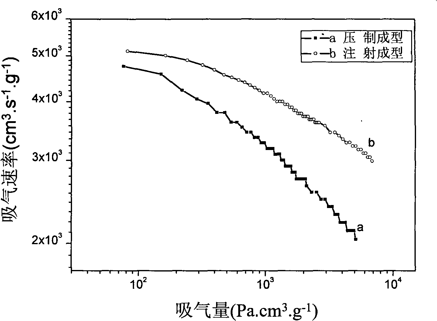
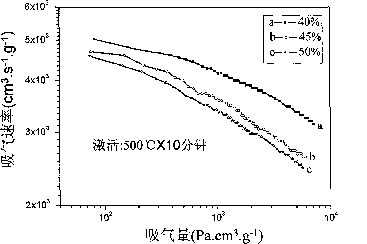
[0021] Put Ti powder with an average particle size of 35 μm and Mo powder with an average particle size of 35 μm in a weight ratio of 9:1 and put them into a mixer, and mix them for 20 hours under the protection of Ar gas to make a raw material powder. 60% of paraffin, 14% of high-density polyethylene, 14% of polypropylene and 12% of hard acid are uniformly mixed according to the weight percentage to prepare the binder. The mixed raw material powder and binder are mixed on a mixer at a volume ratio of 40:60, and the mixing temperature is 150°C. After mixing for 3 hours, it is cooled to room temperature and crushed into injection feed. The feed material is injection-molded on an injection molding machine, the injection temperature is 175° C., and the injection pressure is 70 MPa. Degrease the injection blank in trichlorethylene for 8 hours, then take out the blank and dry it in a vacuum oven at a temperature of 80°C for 3 hours, then heat and degrease the dried blank in a vacuu...

Embodiment 2

[0023] The operating method and process conditions are basically the same as in Example 1, the only difference being that the volume ratio of the raw material powder loading to the binder is 45:55. The air-absorbing element prepared by this process has a porosity of 55%, and the ten-minute hydrogen absorption rate S 10分钟 3728.73cm 3 .s -1 .g -1 , 60-minute inspiratory capacity Q 60分钟 3299.64Pa.cm 3 .g -1 .

Embodiment 3

[0025] The operation method and process conditions are basically the same as in Example 1, the only difference being that the volume ratio of the raw material powder loading to the binder is 50:50. The getter element prepared by this process has a porosity of 51%, and the tenth-minute hydrogen uptake rate S 10分钟 3587.65cm 3 .s -1 .g -1 , 60-minute inspiratory capacity Q 60分钟 3141.37Pa.cm 3 .g -1 .


PUM

PropertyMeasurementUnit
particle sizeaaaaaaaaaa
porosityaaaaaaaaaa

Abstract

The invention provides a method for preparing an electric vacuum inspiration element by using powder injection molding, which belongs to the electric vacuum inspiration element manufacturing technical field. The preparation technology is as follows: Ti powder and Mo powder taken as raw materials are mixed in a mixer, the evenly-mixed raw material powder and adhesive are mixed according to the volume ratio, mixed in a mixing roll, cooled, then crushed into injection feedstock, and subject to the injection molding, two-step debinding process treatment is adopted to a blank formed by the injection molding, the blank formed by the injection molding undergoes solvent debinding and vacuum thermal debinding then, and finally vacuum sintering is carried out to the debound blank to prepare the vacuum inspiration element. The method has the advantages that: the method can prepare the inspiration elements with complicated shape and high dimension accuracy to meet the requirement of spaces with various shapes of various electric vacuum devices to the complicated shape and the dimension accuracy of the inspiration elements. The aperture and the degree of porosity of the product are evenly controlled, and the degree of porosity of the inspiration element can reach more than 50 percent.

Description

technical field [0001] The invention belongs to the technical field of preparation of electric vacuum suction components, in particular to a method for preparing electric vacuum suction components by powder injection molding. Background technique [0002] In the field of electric vacuum, various electric vacuum devices, such as neutron tubes, traveling wave tubes, microwave tubes, laser tubes, photoelectric tubes, electric light sources, etc., all require certain vacuum conditions to work properly. But in fact, during the normal operation or storage of this kind of electric vacuum device, due to the results of adsorption, analysis, ionization removal, bombardment degassing and decomposition, and various surface chemical reactions, the type and partial pressure of the residual gas in the device Changing often. On the basis of gas analysis, combined with the characteristics of different electric vacuum devices, different types of getter components must be used to ensure a goo...

Claims


Application Information

Patent Timeline
Patent Type & Authority Applications(China)
IPC IPC(8): H01J7/18H01J9/39B22F3/00
Inventor 张艳尉秀英秦光荣李腾飞赵振梅杜军毛昌辉苑鹏熊玉华
Owner GRIMAT ENG INST CO LTD
Why Eureka
Try Eureka