Electric car charger

A technology for chargers and electric vehicles, applied in electric vehicles, current collectors, battery circuit devices, etc., can solve the problems of no, frequency instability, frequency instability, etc., and achieve the effect of reliable technology, low price, and prolonging life.

Inactive Publication Date: 2008-10-22
许爱国
View PDF0 Cites 6 Cited by
  • Summary
  • Abstract
  • Description
  • Claims
  • Application Information

AI Technical Summary

Problems solved by technology

[0003] Although the chargers currently on the market also use positive pulse charging and short-term negative pulse discharge, the pulse waveform and frequency of this charger are designed at the front high voltage of the circuit, relying on a dedicated chip (PWM) circuit released The output pulse waveform and frequency, the signal is converted by the back-end multi-level circuit, and when it reaches the low-voltage output of the main power supply, the waveform is messy and the frequency is unstable
The positive and negative square wave pulse signals are directly connected to the final pulse current output tube. When the square wave pulse is at a low level and the main power is turned off, it will cause loss to the current output tube. At the same time, when the discharge negative pulse signal appears, The output of the power supply cannot be turned off quickly and cleanly, and the short-term discharge cannot be simply and powerfully
Therefore, the current charger cannot well meet the above three requirements. Its waveform is messy, the frequency is unstable, and the main power output cannot be completely turned off when discharging. It is not a negative pulse charger in the true sense and cannot achieve The effect of prolonging the service life of the battery

Method used


Image

  • Electric car charger
  • Electric car charger

Examples


Embodiment Construction

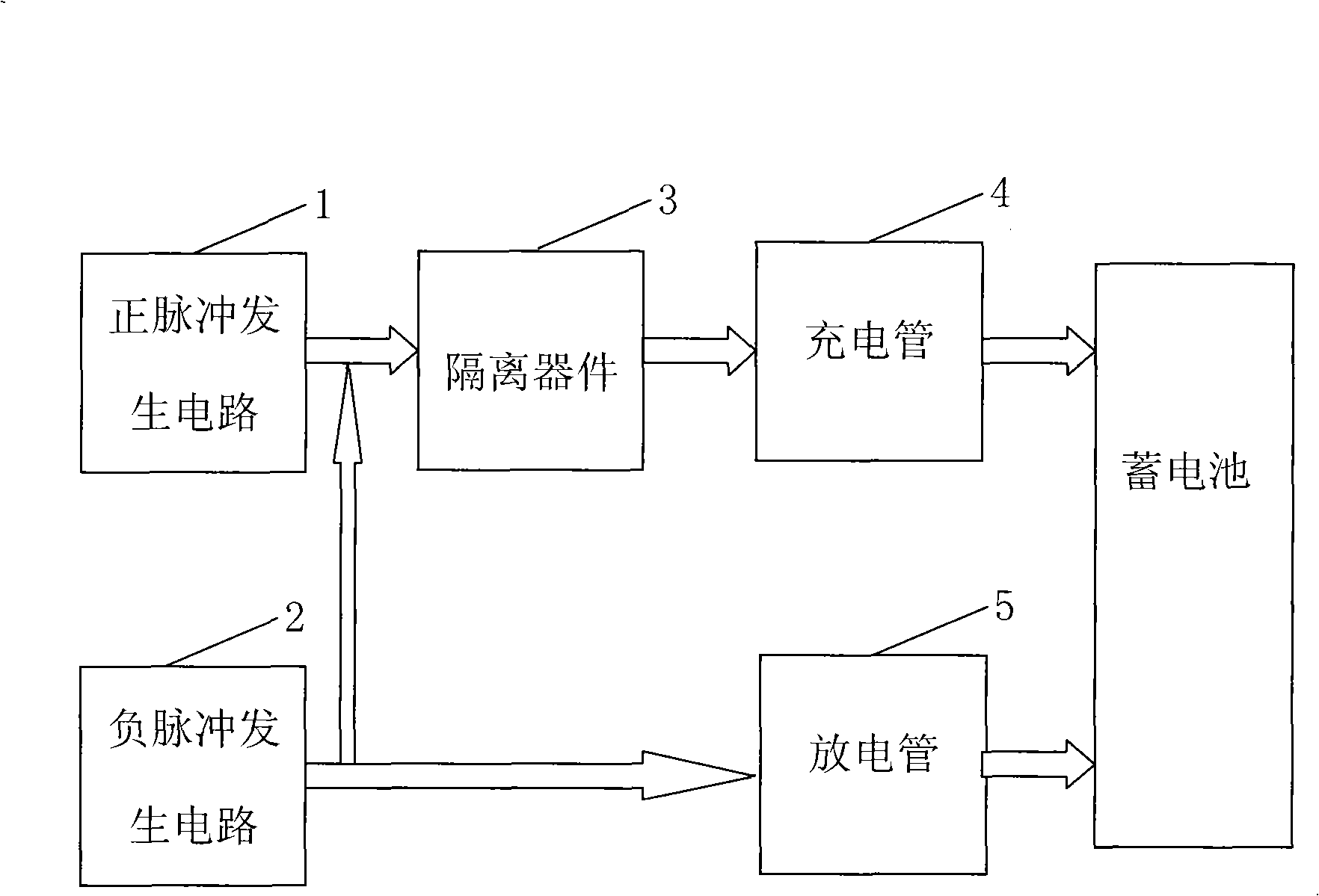
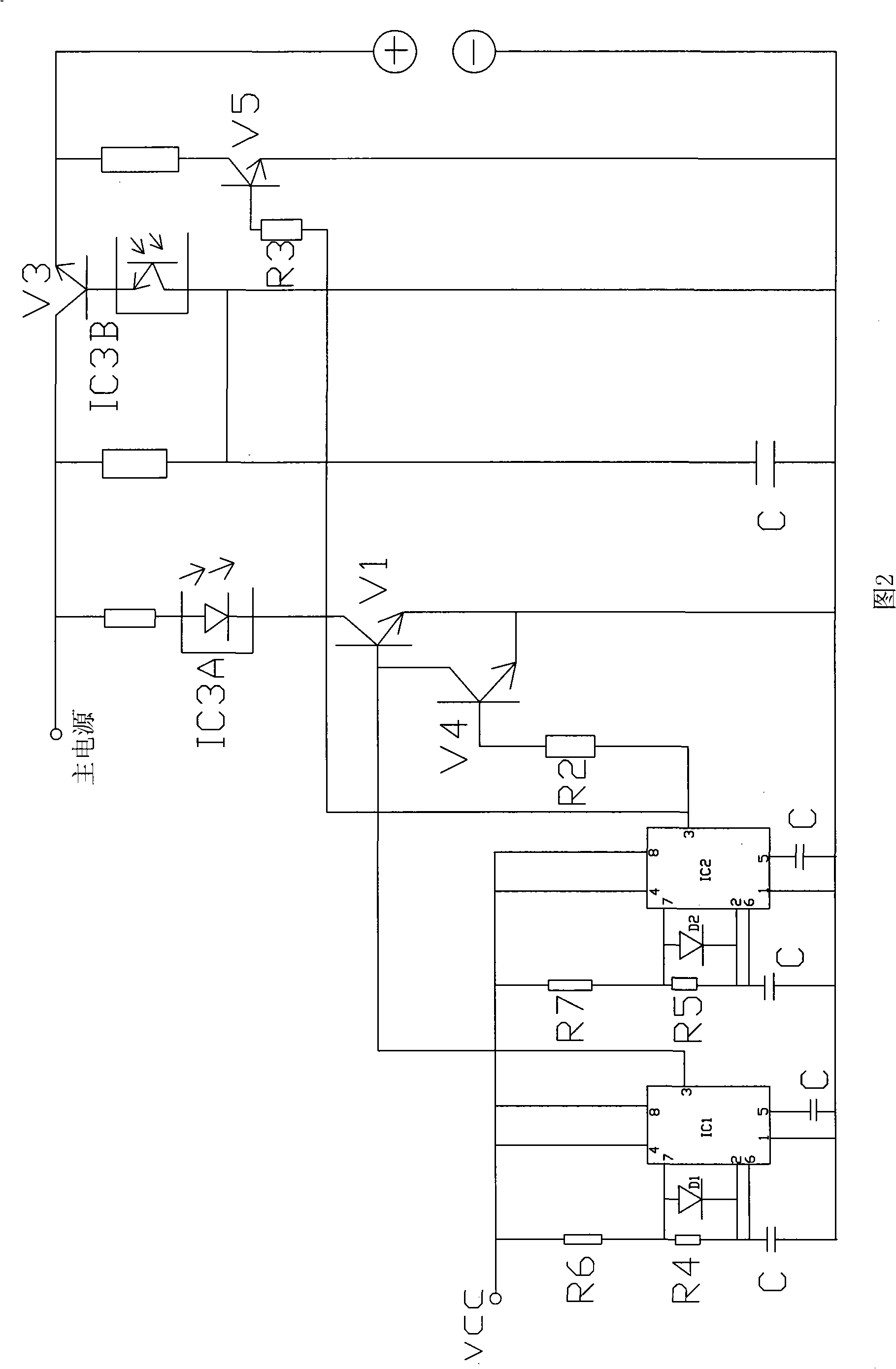
[0015] refer to figure 1 , 2, electric vehicle charger, including positive pulse generating circuit 1, negative pulse generating circuit 2, isolation device 3, charging tube 4, discharge tube 5, when the positive pulse generating circuit 1 and negative pulse generating circuit 2 both adopt 555 Base integrated circuits IC1, IC2, 555 time base integrated circuits IC1, IC2 are connected to the final end of the low-voltage output of the main power supply, the output end of the positive pulse generating circuit 1 is connected to the charging tube 4 through the isolation device 3, and the output of the negative pulse generating circuit 2 The terminal is connected to the discharge tube 5, and both the charging tube 4 and the discharge tube 5 are connected to the storage battery to be charged. The isolation device 3 adopts an optocoupler IC3. The charging tube 4 adopts the third triode V3, and the discharge tube 5 adopts the fifth triode V5. A fourth resistor R4 is also connected to...


PUM


Abstract

The invention discloses an electric vehicle charger. The charger comprises a positive pulse generation circuit, a negative pulse generation circuit, an isolation part, a charging tube and a discharging tube, wherein the positive pulse generation circuit and the negative pulse generation circuit both adopt the 555 time base integrated circuit which is connected on the utmost back end of low voltage output of a main power supply; an output end of the positive pulse generation circuit is connected with the charging tube by the isolation part, and an output end of the negative pulse generation circuit is connected with the discharging tube; and the charging tube and the discharging tube are both connected with the storage battery to be charged. The charger of the invention has the advantages that interferences on pulse waveforms and frequency signals, caused by the multistage conversion of circuit, are avoided; due to the adoption of optical coupling isolation between positive and negative square wave pulse signals and a last stage pulse current output tube, the wear of a current output tube caused by the switchoff of the main power supply is avoided when the square wave pulse is at low level, and the output of the power supply can be quickly and clearly switched off; therefore, in practice, the invention can effectively prolong service lives of the charger and the storage battery.

Description

【Technical field】 [0001] The invention relates to a charger for an electric vehicle storage battery, in particular to an electric vehicle charger with adjustable positive and negative square wave pulses. 【technical background】 [0002] During the use of electric vehicles, the battery needs to be charged repeatedly to provide power. When charging the battery, the positive pulse current can be used to quickly charge the battery; the negative pulse is used to discharge the battery briefly during the charging interval, which can eliminate polarization, increase the acceptance capacity of the plate, reduce the charging temperature, and prolong the service life of the battery. But to really achieve this effect, the following three conditions must be met: 1. Accurate square wave pulse and frequency; 2. Appropriate discharge interval time; 3. When discharging, the main power output must be turned off in time and completely. [0003] Although the chargers currently on the market als...

Claims


Application Information

Patent Timeline
IPC IPC(8): H02J7/00
Inventor 许爱国
Owner 许爱国
Why Eureka
Try Eureka