Laser-electric resistance seam welding in-phase compound welding method of frame-covering structure

A skeleton structure, resistance seam welding technology, applied in laser welding equipment, roller electrode welding, welding equipment, etc., can solve the problems of narrow weld seam and low shear strength of weld seam, improve weld seam structure, improve static load and fatigue resistance, and improve the effect of mechanical properties

Inactive Publication Date: 2008-11-19
HARBIN INST OF TECH
View PDF0 Cites 18 Cited by
  • Summary
  • Abstract
  • Description
  • Claims
  • Application Information

AI Technical Summary

Problems solved by technology

[0005] The purpose of the present invention is to solve the problems of narrow weld seam, low weld shear strength, and a large number of air holes on the overlapping surface of skin and skeleton when a single laser welding skin skeleton structure is used, and to design a laser-skinned skeleton structure. Resistance Seam Welding Simultaneous Hybrid Welding Method

Method used


Image

  • Laser-electric resistance seam welding in-phase compound welding method of frame-covering structure
  • Laser-electric resistance seam welding in-phase compound welding method of frame-covering structure
  • Laser-electric resistance seam welding in-phase compound welding method of frame-covering structure

Examples


specific Embodiment approach 1

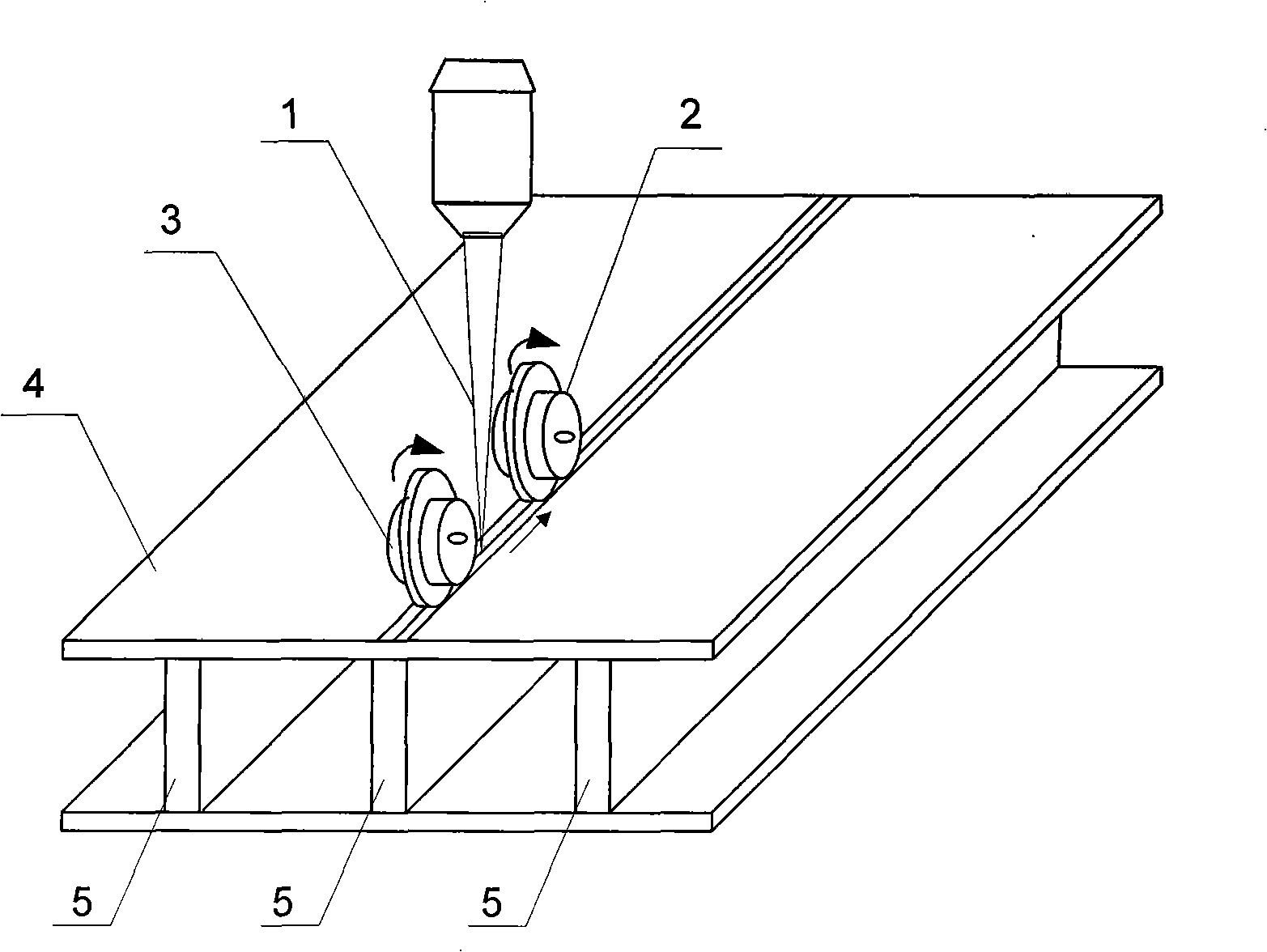
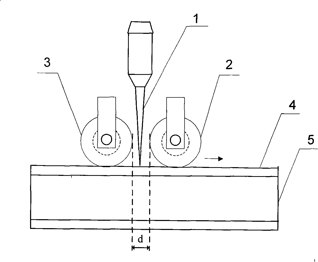
[0014] Specific implementation mode one: the following combination figure 1 , figure 2 , Figure 6-Figure 9 This embodiment is described. In this embodiment, laser welding and resistance seam welding are used for synchronous composite welding of the workpiece to be welded with a skin skeleton structure; The weld seam formed at the contact between the skin 4 and the skeleton 5 is arranged front and back on the upper top face of the skin 4, and while moving forward, presses the skin 4 to the skeleton 5 below it, during the welding process , the laser beam 1 is always located in the middle of the first roller electrode 2 and the second roller electrode 3 .

[0015] During welding, the skin 4 and the skeleton 5 are closely attached by the synchronous pressurization of the first roller electrode 2 and the second roller electrode 3, and the forward movement of the workbench fixing the skin 4 and the skeleton 5 can further Drive the rotation of the first roller electrode 2 and th...

specific Embodiment approach 2

[0017] Embodiment 2: The difference between this embodiment and Embodiment 1 is that the type of laser beam 1 is CO 2 Gas laser beam, YAG solid-state laser beam, semiconductor laser beam or fiber laser beam, and others are the same as the first embodiment.

specific Embodiment approach 3

[0018] Embodiment 3: The difference between this embodiment and Embodiment 1 is that the resistance seam welding current is direct current, alternating current or pulse current, and the others are the same as Embodiment 1.


PUM

PropertyMeasurementUnit
diameteraaaaaaaaaa
diameteraaaaaaaaaa
radiusaaaaaaaaaa

Abstract

A laser and electric-resistance seam-welding synchronous composite welding method for an envelope-framework structure relates to a novel laser and electric-resistance seam-welding synchronous composite welding method, belongs to the welding field, and aims to solve the problems in welding the envelope-framework structure by the single laser, such as narrow seam, low shear strength of the seam, a plurality of air vents on the faying surface of the envelope and the framework. The invention aims at the workpiece with the envelope-framework structure to be welded, and adopts the laser and the electric-resistance seam-welding synchronous composite welding; the electric-resistance seam-welding adopts double-roller single-side welding, two roller electrodes are disposed on the front and the back sides of the upper top surface of the envelope along the seam formed by the contact of the envelope and the framework, so that the envelope is pressed to the lower framework in the travel forward, and the laser beam is always positioned in the middle position of the two roller electrodes during the welding process. The seam formed by the welding method can improve the shear strength more than twice in comparison with the base material, and the air vent amount per area can be reduced from about 10% to about 2% of the laser welding.

Description

technical field [0001] The invention relates to a novel composite welding method of laser and resistance seam welding, which belongs to the field of welding. Background technique [0002] With the increasing awareness of energy conservation and environmental protection in the automotive industry, as well as the requirements of aerospace and military industries for weight reduction and high structural resistance, more and more structural designs use skin-skeleton connections. Compared with riveting and bonding, welding has high production efficiency and high joint strength, and is the most important method for connecting skin skeleton structural parts. However, traditional welding methods such as arc welding and plasma arc welding have large heat input, low welding speed, large welding stress and deformation; and due to the large size of the structure, it is difficult to apply brazing or diffusion welding and other connection methods. [0003] Laser welding has the advantage...

Claims


Application Information

Patent Timeline
Patent Type & Authority Applications(China)
IPC IPC(8): B23K28/02B23K26/24B23K11/06B23K26/346
Inventor 陈彦宾李俐群雷正龙陶汪张新戈
Owner HARBIN INST OF TECH
Why Eureka
Try Eureka