Thin stator, axialclearance brushless vibrating motor with the stator

A type of stator and stator technology, applied in the field of axial gap type brushless vibration motor, can solve the problems that the deflection angle cannot be increased, the starting torque is reduced, the thickness of the hollow armature winding is reduced, and the torque is reduced, so as to improve reliability , strong impact resistance, reliable insulation effect

Inactive Publication Date: 2008-11-19
TOKYO PARTS IND CO LTD
View PDF4 Cites 6 Cited by
  • Summary
  • Abstract
  • Description
  • Claims
  • Application Information

AI Technical Summary

Problems solved by technology

[0013] However, in order to reliably start even if either the center of the magnetic pole of the magnet or the neutral region of the magnetic pole stops at the position of the braking torque generating part, it is necessary to deliberately deviate the braking torque generating part from the center of the winding , so when placing the braking torque generating part to the inner diameter part of the hollow armature winding, if the inner diameter of the winding is small, there is a problem that the deflection angle cannot be increased
Also, if the braking torque generating part does not deviate from the center of the winding at a predetermined angle, there is a problem that the position of the effective conductor part that contributes to the torque is sacrificed,

Method used


Image

  • Thin stator, axialclearance brushless vibrating motor with the stator
  • Thin stator, axialclearance brushless vibrating motor with the stator
  • Thin stator, axialclearance brushless vibrating motor with the stator

Examples


no. 1 Embodiment approach

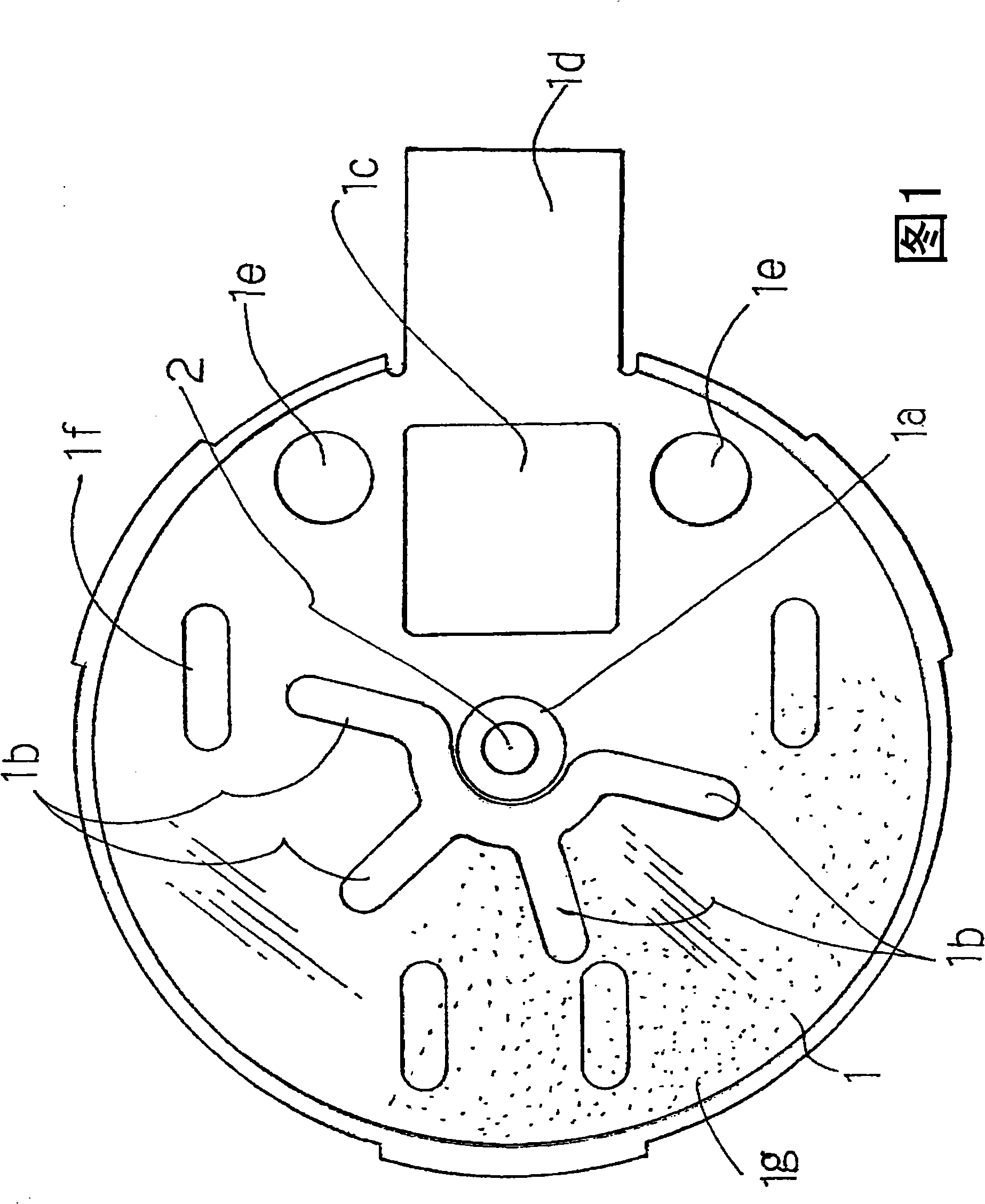
[0035] The bracket 1 constituting the stator according to the present embodiment shown in FIG. 1 is formed of a nonmagnetic or weakly magnetic stainless steel thin plate with a thickness of about 0.2 mm. Then, the proximal end of the shaft 2 is fixed to the shaft support portion 1a at the center of the bracket 1 from the outside (inside the drawing of FIG. 1 ) by laser welding L1 (see FIG. 5 described later). And, on the outside of the diameter direction of the shaft 2 of the bracket 1, there are four through holes 1b that are connected on one side of the center and expand into a V shape in the diameter direction. The magnetic pole opening angles (60°) of the axial gap magnets 10 (see FIG. 5 ) of the combined rotor described above are equal. In addition, the bracket 1 can also be a conductive or non-conductive material.

[0036] In order to start the rotor reliably even if either the center of the magnetic pole or the neutral region of the magnetic pole of the axial gap type ...

no. 2 Embodiment approach

[0051] This embodiment is an example of an axial gap type brushless vibration motor using the stator S according to the first embodiment.

[0052] The eccentric rotor R combined to the stator S is shown in Fig. 5 . That is, the rotor case 7 is formed with a magnetic stainless steel flat portion 7a with a thickness of about 0.2 mm, an outer peripheral side hanging portion 7b, and an inner diameter side hanging portion 7c, and an arc-shaped tungsten eccentric weight 8 is fixed by soldering or laser welding. The sintered oil-impregnated bearing 9 is fixed to the radially inner hanging portion 7c on the outer peripheral side hanging portion 7b by caulking, laser welding, soldering, or the like. The axial gap magnet 10 magnetized into six poles is fixed inside the flat portion 7a by bonding or the like.

[0053] Furthermore, as a method of fixing the eccentric weight 8, besides the above-mentioned method, a method such as extending the outer periphery of the rotor case 7, riveting...


PUM

PropertyMeasurementUnit
Thicknessaaaaaaaaaa
Thicknessaaaaaaaaaa
Thicknessaaaaaaaaaa

Abstract

The invention provides a thin stator and an axial-gap type brushless oscillating motor with the thin stator, which can be fully left out thickness to arrange a braking torque generating component, remove a part of a winding configuration region of a stator base, and determine the thickness of a winding so as to achieve the aim of increasing a torque. A plurality of coreless armature windings (5) are configured on a support (1) of a non-magnetic or weak-magnetic substance which configures a shaft supporting part (1a) in the center via an insulating protection film. The stator base (4) is configured without overlapping the coreless armature windings (5). A drive circuit component (D) is configured on the stator base (4). The braking torque generating component (3) is embedded in the support (1). The braking torque generating component (3) is provided with a plurality of braking torque generating part (3a) forming a magnetic pole field angle of a magnet of a combined rotor.

Description

field of invention [0001] The present invention relates to a thin stator suitable for a silent notification unit of a mobile communication device, and an axial gap type brushless vibration motor provided with the stator. Background technique [0002] As an axial gap type brushless vibration motor, a centerless slotless motor having a single shaft has been proposed (see Patent Document 1 and Patent Document 2). [0003] In addition, as a brushless vibration motor with a drive circuit, we know a heart-shaped non-circular motor in which the armature winding is wound on a plurality of salient poles arranged in equal parts, and the drive circuit part is arranged on the stator side. (Refer to Patent Document 3). [0004] However, the above-mentioned motor has a large lateral dimension, poor mounting efficiency of the SMD method arranged on a printed circuit board, and is a heart-shaped motor, so the thickness has to be large, which is not practical. [0005] In addition, there a...

Claims


Application Information

Patent Timeline
IPC IPC(8): H02K7/065H02K21/12H02K21/02H02K3/04
CPCB06B1/04H02K1/16H02K7/065H02K7/075H02K15/03H02K29/03H05K1/0393
Inventor 山口忠男
Owner TOKYO PARTS IND CO LTD
Why Eureka
Try Eureka