Production method of cold cathode flat light source

A planar light source and manufacturing method technology, applied in cold cathode manufacturing, electrode system manufacturing, discharge tube/lamp manufacturing, etc., can solve the problems of light source damage, increase of non-luminous area, exhaust pipe rupture, etc., to improve the yield and production efficiency, improvement of luminance uniformity, and improvement of luminance uniformity

Inactive Publication Date: 2008-12-03
XI AN JIAOTONG UNIV
View PDF0 Cites 6 Cited by
  • Summary
  • Abstract
  • Description
  • Claims
  • Application Information

AI Technical Summary

Problems solved by technology

[0005] (1) Since the internal pressure of the planar light source is much lower than the external atmospheric pressure (about 101.3kPa) during and after the completion of the planar light source, in order to prevent the substrate from being broken by atmospheric pressure, an isolation column is required between the front and rear substrates, thereby increasing the The complexity of the manufacturing process and increased manufacturing costs
[0006] (2) When the isolation column is processed, its height is scattered to a certain extent. Therefore, even with the existence of the isolation column, some areas on the glass substrate of the light source also have certain stress. ), the glass substrate is easy to break, therefore, the yield of flat light source manufacturing is reduced, and the light source is also easily damaged during use
[0007] (3) Due to the existence of isolation columns, the brightness uniformity of the planar light source is reduced
[0008] (4) Since the planar light source has an exhaust pipe, if the exhaust pipe is located on the rear substrate, the thickness of the light source will be increased; area, and the exhaust pipe is also vulnerable to collision and rupture during the use of the flat light source, resulting in damage to the light source

Method used


Image

  • Production method of cold cathode flat light source
  • Production method of cold cathode flat light source
  • Production method of cold cathode flat light source

Examples


Embodiment Construction

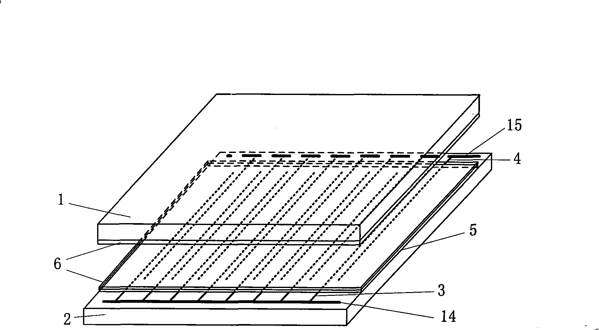
[0047] refer to figure 1 As shown, it consists of a front glass substrate 1 and a rear glass substrate 2. The inner surface of the front glass substrate 1 is equipped with a phosphor layer 6, and the inner surface of the rear glass substrate 2 is equipped with two sets of electrodes, namely X electrodes 3 and Y electrodes. 4. X electrodes 3 and Y electrodes 4 are covered with dielectric layer 5, and the surface of dielectric layer 5 is covered with phosphor layer 6. All X electrodes 3 are connected to lead electrodes 14, and all Y electrodes 4 are connected to lead electrodes 15. A certain distance is maintained between the glass substrate 1 and the rear glass substrate 2 by spacers, the interior is filled with discharge gas, and a certain voltage waveform is applied between the X electrode 3 and the Y electrode 4, a discharge will be generated between the electrodes, and the discharge generated Ultraviolet light excites the phosphor to emit visible light.

[0048] refer to ...


PUM

PropertyMeasurementUnit
softening pointaaaaaaaaaa
thicknessaaaaaaaaaa

Abstract

The invention discloses a manufacturing method of a cold cathode planar light source, sealing materials are coated at the peripheries of a front substrate and a back substrate which are equipped with electrodes, dielectric layers and fluorescent powder layers, the space between the front substrate and the back substrate is not sealed, clamps are used for accurate contraposition of the two substrates, the front and back substrates are further arranged in a closed cavity, the heating and exhaust of the interior of the cavity are carried out, when the vacuum degree achieves 10 to 10 Pa, the exhaust is stopped, a discharge gas is filled in the cavity, the gas filling pressure is 80T/Tr to 101.3T/Tr kPa by selection, T is the temperature of the substrates during the gas filling, Tr is the room temperature, the sealing materials are melt under the high temperature, the temperature of the cavity is then decreased, the sealing materials are gradually cured, thus completely sealing the front and back substrates; when the temperature is decreased to the room temperature, the manufactured cold cathode planar light source is taken out from the cavity, and the internal pressure of the light source is 0.8 to 1 atmospheric pressure. The usage of the manufacturing method can simplify the manufacturing process of the cold cathode planar light source, reduce the manufacturing cost and reduce the thickness of the planar light source.

Description

technical field [0001] The invention belongs to the field of display and lighting source manufacturing, and relates to a method for manufacturing a fluorescent lamp, in particular to a method for manufacturing a cold-cathode planar light source that can be used as a liquid crystal display backlight source and an illumination source. Background technique [0002] In recent years, with the further maturity of production technology and the continuous reduction of manufacturing costs, large-screen liquid crystal displays (LCDs) have been more and more widely used. Flat-panel liquid crystal displays with large information capacity are generally transmissive, requiring a light source behind the liquid crystal panel to realize display. At present, the backlight commonly used in flat-panel liquid crystal displays is a cold cathode fluorescent lamp (CCFL), which has the advantages of high light efficiency and brightness, but its disadvantages are that it takes a long time to reach sa...

Claims


Application Information

Patent Timeline
Patent Type & Authority Applications(China)
IPC IPC(8): H01J9/26H01J9/385H01J9/395H01J9/00C03B23/20G02F1/13357G02F1/1335
CPCY02P40/57
Inventor 胡文波刘震徐伟军王文江郑德修张劲涛
Owner XI AN JIAOTONG UNIV
Why Eureka
Try Eureka