Novel polymer based microfluid reactor suitable for photochemistry reaction and preparation method thereof

A technology of microfluidic reactors and photochemical reactions, applied in chemical instruments and methods, chemical/physical processes, chemical/physical/physical chemical processes, etc., can solve problems such as failure to top, high cost of capping materials, and light transmission. To achieve the effect of process optimization

Inactive Publication Date: 2008-12-10
BEIJING UNIV OF CHEM TECH
View PDF1 Cites 5 Cited by
  • Summary
  • Abstract
  • Description
  • Claims
  • Application Information

AI Technical Summary

Problems solved by technology

However, three main problems still need to be solved: first, the capping of the microfluidic channel to achieve non-blocking, strong connection and sufficient light transmission; second, chemically compatible modification of the substrate and strong bonding with the microchannel pattern; 3. Hydrophilic-lipophilic equilibrium modification of the inner wall of polymer microfluidic channels
However, the use of SU8 to prepare microfluidic reactors still needs to face the following difficulties: First, there is no cheap way to cover SU8 without clogging, and the top of

Method used


Image

  • Novel polymer based microfluid reactor suitable for photochemistry reaction and preparation method thereof
  • Novel polymer based microfluid reactor suitable for photochemistry reaction and preparation method thereof
  • Novel polymer based microfluid reactor suitable for photochemistry reaction and preparation method thereof

Examples


preparation example Construction

[0032] 3. Preparation of Microfluidic Reactor

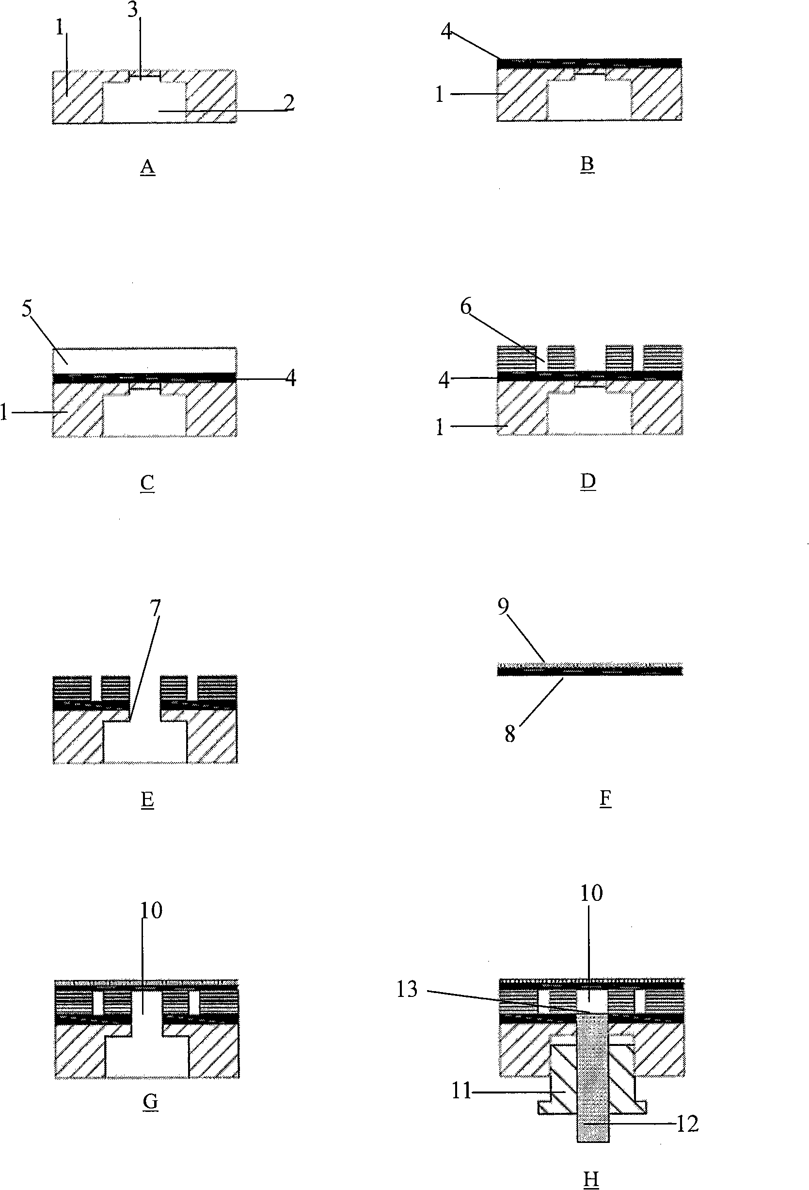
[0033] The construction of the flow channel of the microfluidic reactor adopts photolithography process, and the schematic diagram of the process flow is shown in figure 1 .

[0034] Threaded holes 2 (only one is shown in the figure) are machined at the inlet and outlet positions (bottom) of the PMMA substrate 1. In order to facilitate the spin-coating of the adhesive layer, all inlets and outlets 3 are not opened. figure 1 As shown in A.

[0035] Use EA51 to modify the surface of PMMA matrix 1, such as figure 1 Shown in B.

[0036] Next, spin-coat SU82050 on the surface of EA51 cured adhesive layer 4 to form adhesive layer 5, such as figure 1 C shown. And carry out the three-step process of pre-baking, exposure and post-baking.

[0037] Then, if figure 1 As shown in D, the unexposed part is developed to form the micro channel pattern 6 .

[0038] Then all the imports and exports 7 can be opened up (only one is shown in t...

example 1

[0063] Example 1 prepares the microreactor of polymer microsphere

[0064] Figure 8It is a microfluidic reactor for preparing polymer microspheres (surface functionalization, core-shell structure and other particles). The preparation process of the reactor is as described above. In order to slow down the pressure increase and facilitate the flow of liquid into and out of the microchannel, the inlet and outlet channels of the microfluidic reactor are all designed with a gradually changing width.

[0065] Such as Figure 8 As shown, the polymer microsphere microreactor has three inlet channels 14, 15 and one outlet channel 16, and each terminal has an inlet (outlet) hole 17 with a diameter of 1 mm (only one is marked in the figure). The dispersed phase (such as the oily monomer phase) flows in through the inlet channel 14 in the middle, and the continuous phase (such as the water phase) flows in through the inlet channels 15 on both sides. When the three microfluids pass th...

example 2

[0066] Example 2 prepares the microreactor of nanoparticle

[0067] Figure 9 It is a microfluidic reactor for the preparation of nanoparticles (such as Au, Ag, Co). The preparation process of the reactor is as described above. In order to slow down the pressure increase and facilitate the flow of liquid into and out of the microchannel, the inlet and outlet channels of the microfluidic reactor are all designed with a gradually changing width.

[0068] Such as Figure 9 As shown, the nanoparticle microreactor has three inlet channels 20, 21 and an outlet channel 22, wherein 20 is the first inlet channel, 21 is the second inlet channel, and the terminals of all the inlet and outlet channels have an inlet with a diameter of 1 mm. (Export) hole 23 (only one is marked among the figure). We can add a new reactant to the second inlet 21 to make it mix with the previous microfluidic reaction solution for reaction. The two passages of the first inlet 20 can add different reactant...


PUM

PropertyMeasurementUnit
Thicknessaaaaaaaaaa
Thicknessaaaaaaaaaa
Apertureaaaaaaaaaa

Abstract

The invention relates to a novel polymer-based microfluid reactor applicable to photochemical reaction and the preparation method thereof and belongs to the technical field of the manufacture of the polymer-based microfluid reactor. The preparation method of the reactor comprises: manufacturing a screwed hole with a non-breakthrough top used for connecting external equipment on the inlet and outlet position of a PMMA base; spin coating an EA51 glue layer on the surface of the PMMA for modifying the surface; spin coating an SU8 glue layer on the surface of the EA51 glue layer and carrying out three steps of processes of pre-baking, exposing and post-braking; developing the unexposed part of the SU8 glue layer to form a micro channel pattern; getting through the inlet and the outlet; spin coating an EA51 glue layer on the surface of a BOPP membrane which goes through hydroxylation treatment to form a sealing glue layer; sealing the micro channel pattern; exposing the top sealing layer under close compaction state to lead to complete solidification of the glue layer; thus forming the closed micro channel; screwing the PEEK bolt of an internal tight tube into the screwed hole. The reactor, which is an all-organic transparent microfluid reactor, solves the common problems in the manufacture of the current microfluid reactor and realizes lighting synthesis of nano-particles and polymer microsphere and the like particles.

Description

Technical field: [0001] The invention belongs to the technical field of polymer-based microfluidic reactor manufacturing and a method for controllably synthesizing micron and nanometer particles with the microfluidic reactor. Background technique: [0002] Based on the concept of parallel processing and parallel amplification, the microfluidic reactor can be directly enlarged from the research stage to the large-scale production stage without considering the amplification effect. shows increasing potential in terms of purity. By improving the efficiency and controllability of chemical reactions and reducing the amount of raw materials, microfluidic reactors can minimize the environmental and health risks inherent in traditional batch reactions, such as avoiding large-scale transportation and storage, potential explosions, and poisons. and the leakage of flammable materials, etc. In addition, compared with traditional chemical processes, microfluidic reactors can control th...

Claims


Application Information

Patent Timeline
IPC IPC(8): B01J19/08B01J19/00
Inventor 杨万泰刘佳马育红刘莲英
Owner BEIJING UNIV OF CHEM TECH
Why Eureka
Try Eureka