
Compensation process capable of increasing machine precision of numerical-controlled lathe and magnetic striction compensation mechanism

A technology of machining accuracy and compensation mechanism, applied in metal processing machinery parts, metal processing, metal processing equipment and other directions, can solve the problems of high cost, high price, unsuitable mechanism of action, etc., to suppress chatter, improve processing accuracy, Overcome the effects of technical sophistication

Active Publication Date: 2009-01-07
JIANGSU HAIJIAN +1
View PDF0 Cites 30 Cited by
  • Summary
  • Abstract
  • Description
  • Claims
  • Application Information

AI Technical Summary

Problems solved by technology

Early ultrasonic machining mainly relied on tools for ultrasonic frequency (above 20,000 Hz) vibration, so that the abrasive in the suspension can obtain impact energy, thereby removing the workpiece material to achieve the purpose of processing. This ultrasonic machining technology is not only costly and expensive, but also its role The mechanism is also not suitable for use on machine tools

Method used


Image

  • Compensation process capable of increasing machine precision of numerical-controlled lathe and magnetic striction compensation mechanism
  • Compensation process capable of increasing machine precision of numerical-controlled lathe and magnetic striction compensation mechanism
  • Compensation process capable of increasing machine precision of numerical-controlled lathe and magnetic striction compensation mechanism

Examples


Embodiment Construction

[0040] Below in conjunction with accompanying drawing, the present invention is described in detail:

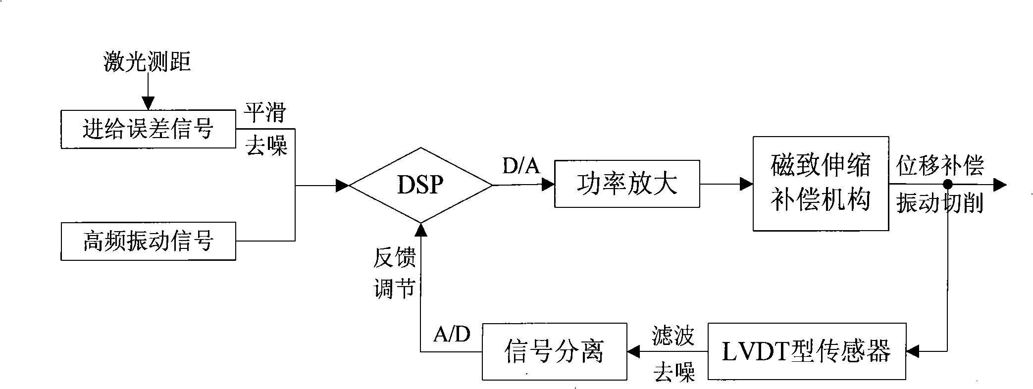
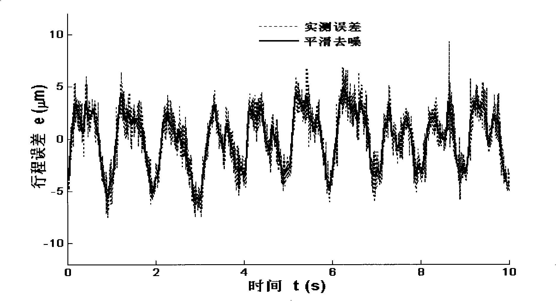
[0041]A method for compensating the accuracy of CNC lathes through compound feed. The main principle of this method is that, in view of the technical difficulties in online detection of machine tool machining accuracy, the feed error within the full stroke range of the machine tool is measured by a dual-frequency laser interferometer. The off-line displacement compensation of the modular magnetostrictive compensation mechanism cooperates with the macro-displacement feed of the CNC lathe for micro-displacement feed; when the error compensation signal is superimposed on the error compensation signal at the same time, when the compensator is driven by a small-amplitude vibration signal with a fixed frequency for vibration cutting, it can Effectively suppress the chatter phenomenon during machine tool cutting, improve the machining accuracy of the workpiece, and complete the stora...


PUM


Abstract

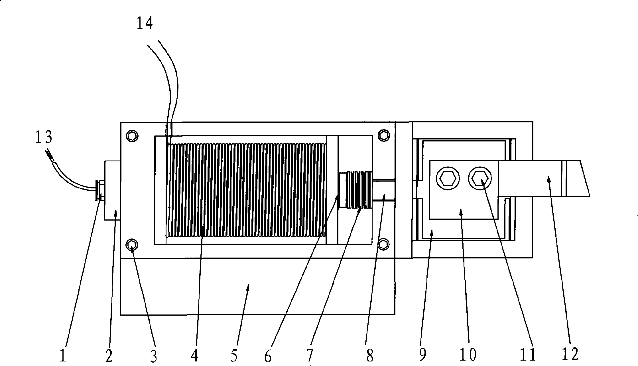
The invention discloses a compensation method for enhancing the machining accuracy of a numerical control machine tool and a magnetostrictive compensation mechanism, in particular to a method for compensating the accuracy of the numerical control machine tool through combined feed and a modularized accuracy compensation mechanism. The method comprises the following steps: aiming to the machine tool, because of a geometrical error formed by a plurality of factors such as manufacture, abrasion, etc., feed errors in a full-stroke range are measured by a dual-frequency laser interferometer; the modularized compensation mechanism is driven to produce the corresponding displacement compensation quantity through power amplification after an error signal is pretreated; the micro-displacement feed is performed in cooperation with the macro displacement feed, so as to correct the accuracy of the machine tool. High-frequency vibration signals are superposed as a drive compensation mechanism for driving the voltage to perform vibration cutting, thereby effectively inhibiting a flutter phenomenon caused by friction during cutting, and enhancing the machining accuracy. An LVDT inductive displacement transducer is mounted at the tail end of an elastic micro-displacement mechanism for position feedback regulation; furthermore, the closed-loop control is formed through real-time control operation in a DSP chip to realize precise positioning.

Description

technical field [0001] The patent of the present invention relates to a method for improving machining accuracy of machine tools through compound feed and a modular error compensation device. Specifically, it relates to a method for compensating machine tool errors through micro-displacement compensation and vibration cutting generated by giant magnetostrictive actuators. And a method and a device for improving the machining accuracy of a machine tool. Background technique [0002] In the research and development process of precision and ultra-precision machining technology, precision and ultra-precision machine tools play a decisive role. The accuracy of traditional ultra-precision machine tools is mainly achieved by the accuracy of the reference components of the machine tool. However, it is very difficult to improve the machining accuracy by continuing to improve the accuracy of ultra-precision machine tool components, and some errors in machining are difficult to elimina...

Claims


Application Information

Patent Timeline
Patent Type & Authority Applications(China)
IPC IPC(8): B23Q15/013B23Q17/00
Inventor 王兴松曹军毛燕王晨马魏
Owner JIANGSU HAIJIAN
Learn More