Lamination-vacuum pressure pouring process of micro conductive retractor collar

A conductive slip ring, vacuum pressure technology, applied in slip ring manufacturing, circuits, current collectors, etc., can solve the problems affecting the reliability of miniature conductive slip ring components, the difference in the thickness of the filling layer, and the poor mutual insulation performance. Environmental adaptability and reliability of work, guarantee consistency and reliability of work, effect of good integrity

Inactive Publication Date: 2009-01-07
JIUJIANG JINGDA MEASUREMENT TECH
View PDF0 Cites 10 Cited by
  • Summary
  • Abstract
  • Description
  • Claims
  • Application Information

AI Technical Summary

Problems solved by technology

[0005] Among the above two manufacturing processes, the biggest advantage of the first manufacturing process is that the conductive slip ring components are firmly bonded into a whole through the bonding of epoxy resin to each conductive ring, and the conductive slip ring components are anti-vibration. It has a strong ability to resist harsh environments, and its performance is very stable, but its main problem is: when producing micro-miniature conductive slip ring components, this process relies on the vacuum pressure of epoxy resin to be poured onto the conductive ring body. The narrow gap (0.2mm) between the conductive rings is used to realize the bonding and insulation between the conductive rings. Because the gap between the conductive rings of the miniature conductive slip ring assembly is too small and the pouring depth is large (5mm), the epoxy resin When vacuum pressure casting is used to fill the gap, the casting pressure is different in the gap at different positions and at different positions in the same gap, and the conductive ring with a small thickness has very low rigidity, and it is difficult to resist the deformation of the conductive ring caused by different casting pressures. Side pressure, under the influence of this side pressure, each conductive ring will produce different degrees of deformation, so that the epoxy resin filling layer between the conductive rings is different between different conductive rings and in different positions in the same conductive ring gap. There is a big difference in the thickness of the epoxy resin filling layer, and there may even be empty glue in some places (that is, the epoxy resin cannot

Method used


Image

  • Lamination-vacuum pressure pouring process of micro conductive retractor collar

Examples


Embodiment Construction

[0014] The present invention will be described in further detail below in conjunction with the embodiments and with reference to the accompanying drawings. ,

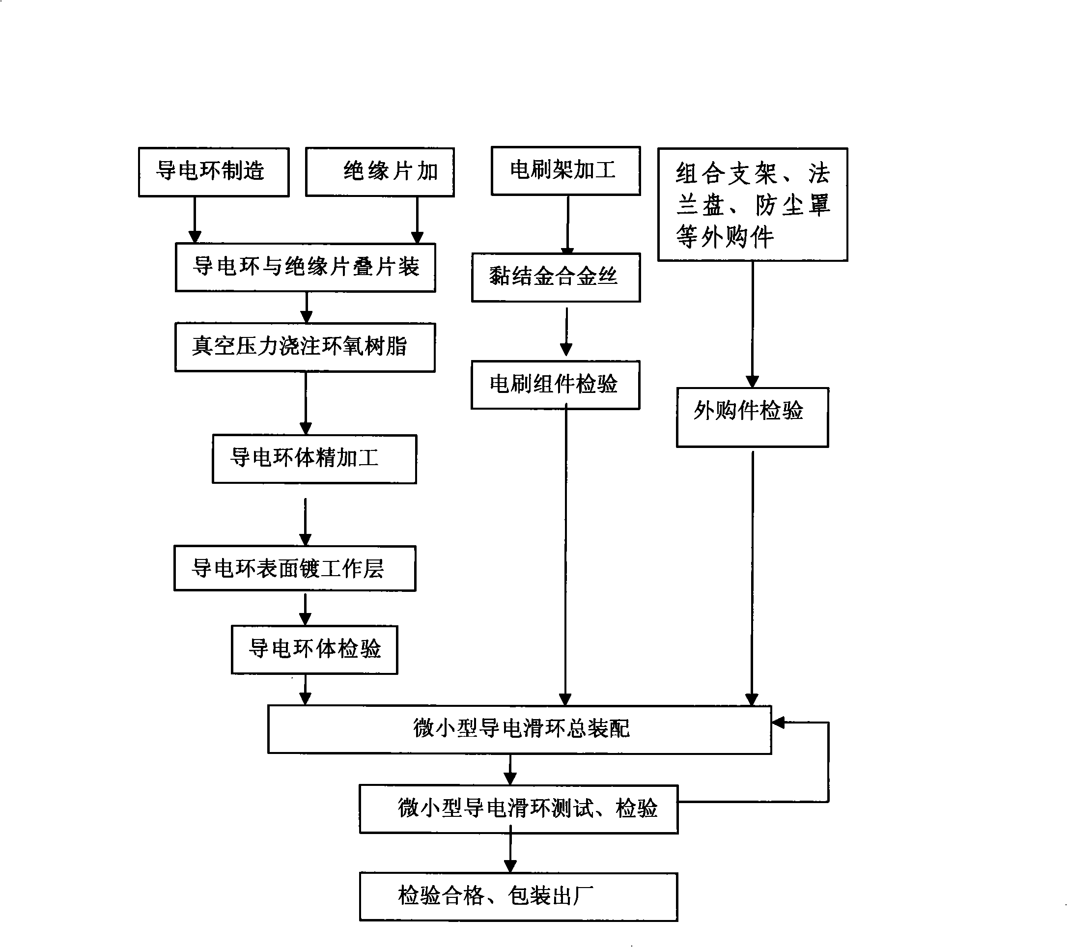
[0015] The present invention includes conductive ring processing technology, brush holder processing technology and miniature conductive slip ring assembly technology, wherein the conductive ring processing technology includes conductive ring manufacturing, insulating sheet processing, conductive ring body finishing, conductive ring surface plating working layer and Conductive ring body inspection and other steps. The brush holder processing technology consists of three steps: brush holder processing, bonding gold alloy wire and brush assembly inspection. After the conductive ring body inspection and brush assembly inspection, the combined bracket, Structural parts such as flanges and dust covers are inspected, and then the processed conductive ring body, brush holder assembly, combined bracket, flange, and dust cover a...


PUM


Abstract

The invention discloses a lamination-vacuum pressure pouring technology of a microminiature conducting slip ring, which comprises the processing technology of a conducting ring, the processing technology of a brush holder and the general assembly technology of the microminiature conducting slip ring; after the conducting ring body and the brush component are inspected, the bought-in component inspection is carried out on the bought-in components such as a combination support, a flange, a dust shield, and the like; and then the conducting ring body, the brush holder component and the bought-in components are assembled into the microminiature conducting slip ring, and then tested and inspected; and after passing the inspections, the conducting ring body, the brush holder component and the bought-in components are packed and delivered. The lamination-vacuum pressure pouring technology of the microminiature conducting slip ring is characterized in that: after the conducting ring is manufactured and an insulating strip is processed, the conducting ring and the insulating strip are firstly laminated for assembly, epoxy resin is poured at the vacuum pressure, and then fine machining is performed on the conducting ring body. The lamination-vacuum pressure pouring technology of the microminiature conducting slip ring has the advantages that the two conducting rings are both mutually insulated and reliably connected, and rubber layers thereof can not fall off, the environmental suitability and operational reliability of the products are improved, the rate of defective products is low, and the performance of the product can correspond to that of the similar products abroad.

Description

technical field [0001] The invention relates to a conductive slip ring, in particular to a lamination-vacuum pressure casting process of a miniature conductive slip ring. Background technique [0002] The conductive slip ring is a precise electrical signal transmission device that realizes the multi-channel electrical signal (or current) transmission between two relative rotating mechanisms that requires no mutual interference. The conductive slip ring assembly is composed of a conductive ring body, a brush assembly, a combined bracket with precision bearings, a flange (or corresponding interface parts), and a dust cover. Its technical principle is: installed on the combined bracket equipped with precision bearings, there are multiple wires on the rotating mechanism in the rotating part connected to multiple mutually insulated conductive rings on the conductive ring body, and the brush assembly is installed on the combined bracket The relatively fixed part of the brush asse...

Claims


Application Information

Patent Timeline
IPC IPC(8): H01R39/64H01R43/10H01R39/38B22D18/00
Inventor 汤文军王永松邓军
Owner JIUJIANG JINGDA MEASUREMENT TECH
Why Eureka
Try Eureka