Hydrocarbons recovery method

A hydrocarbon recovery and hydrocarbon technology, applied in separation methods, chemical instruments and methods, dispersed particle separation, etc., can solve the problems of inconvenient operation, large adsorbent amount, and increased equipment investment.

Active Publication Date: 2009-01-14
CHINA PETROLEUM & CHEM CORP +1
View PDF3 Cites 23 Cited by
  • Summary
  • Abstract
  • Description
  • Claims
  • Application Information

AI Technical Summary

Problems solved by technology

When this patent is aimed at the purification of hydrocarbon waste gas with high concentration, there are also the above-mentioned dangerous safety problems caused by excessive heat of adsorption
[0008] Although other types of non-flammable adsorbents can also be used in the adsorption process

Method used


Image

  • Hydrocarbons recovery method
  • Hydrocarbons recovery method

Examples


Embodiment 1

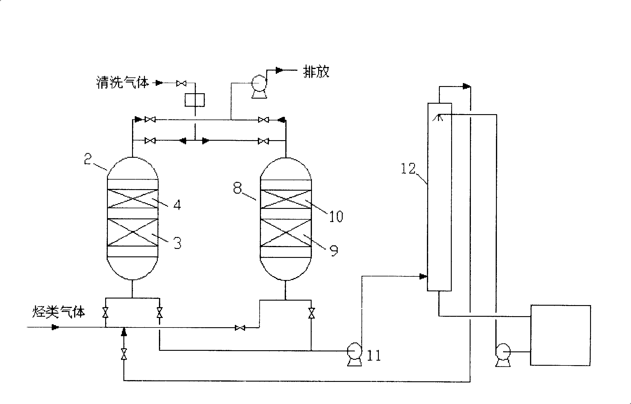
[0029] In this embodiment, the two-stage adsorption method is used to process the breathing gas of the oil tank, and the gas is operated from bottom to top. The total hydrocarbon concentration is 35% (volume), and the vacuum desorption gasoline absorption method is used to recover hydrocarbons. The lower adsorbent is commercially available silica gel. , specific surface area 713m 2 / g, pore volume 0.39ml / g, average pore diameter 2.2nm. The upper layer is commercially available activated carbon with a specific surface area of ​​1077m 2 / g, the pore volume is 0.52ml / g, the average pore diameter is 1.5nm, and the absorption liquid is gasoline. The volume ratio of silica gel adsorbent to activated carbon adsorbent is 60:40, and the total volume space velocity is 1000h -1 , Adsorption takes 2h to be regenerated. After the process is processed, the total hydrocarbon concentration of the outlet gas is less than 20ppm, and the recovery rate is 100% (by mass). The adsorption ambien...

Embodiment 2

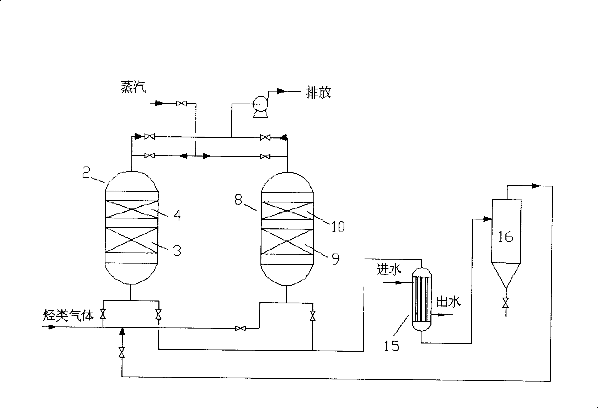
[0033] In the present embodiment, the waste gas is 1% (volume) toluene, and the lower layer is a commercially available zeolite with a specific surface area of ​​750m 2 / g, the pore volume is 0.4ml / g, the upper layer is activated carbon, and the specific surface area is 884m 2 / g, pore volume 0.4ml / g, average pore diameter 1.5nm, steam desorption, condensation temperature 25°C, volume ratio of zeolite to activated carbon 30:70, total volume space velocity 3000h -1 . After being treated by the process, the outlet toluene concentration is less than 3ppm, and the recovery rate is more than 99.99% (mass). The adsorption ambient temperature is 28°C, the lower adsorption temperature is 35°C, and the activated carbon layer temperature is 45°C.

Embodiment 3

[0035] By the process of embodiment 1, the volume ratio of silica gel adsorbent and active carbon adsorbent is 80: 20, and total volume space velocity is 800h -1 , Adsorption takes 2 hours to regenerate. After the process is processed, the total hydrocarbon concentration of the outlet gas is less than 20ppm, and the recovery rate is 100% (by mass). The adsorption ambient temperature is 22°C, the maximum temperature of the silica gel adsorption bed is 40°C, and the temperature of the activated carbon bed is 50°C.


PUM

PropertyMeasurementUnit
Specific surface areaaaaaaaaaaa
Pore volumeaaaaaaaaaa
Average pore sizeaaaaaaaaaa

Abstract

The present invention relates to a hydrocarbon recovery method, which adopts solid absorbent to adsorb hydrocarbon. Mixed gas containing hydrocarbon first passes through uninflammable inorganic absorbent and then inflammable absorbent; the uninflammable inorganic absorbent contains silica gel, zeolite or alumina; the inflammable absorbent contains activated carbon or activated carbon fibers; and the volume ratio between the uninflammable absorbent and the inflammable absorbent is between 20 : 80 and 80 : 20. The absorbents are regenerated by adopting a vacuum regeneration method or a steam regeneration method. The present invention provides a method and a device which are used for the purification and recovery of high-concentration hydrocarbon waste gases (VOCs, organic waste gases, oil gas). Compared with the prior art, the method has the advantages of low temperature rise of the absorbents, high safety performance, high recovery benefit, etc., and the concentration of VOCs at the emission outlet of the device can meet the national emission standard. The method can be used in places and cases producing high-concentration waste hydrocarbon gases, such as oil tanks, oily sewage tanks, hydrocarbon produced in the process of oil filling in tankers and VOCs produced in the process of hydrocarbon processing.

Description

technical field [0001] The invention provides a method for recovering hydrocarbons, especially a method for recovering hydrocarbons by adopting an adsorption method. Background technique [0002] Crude oil, gasoline, some chemical solvents such as benzene, toluene, xylene production workshops, coatings and other organic solvents contain or have highly volatile light hydrocarbon components. During the transportation, transfer, and sales of processed products (gasoline, diesel, etc.), a large amount of oil vapor (oil gas) escapes into the atmosphere. The oil vapor mentioned here is usually called VOCs, also known as non-methane hydrocarbons , collectively referred to as hydrocarbon gases. [0003] In oil refining enterprises, various storage tanks, oil separation flotation tanks in sewage treatment plants, etc. also emit relatively high concentrations of hydrocarbons. These hydrocarbons have complex components, which not only cause hydrocarbon loss, but also often cause odor ...

Claims


Application Information

Patent Timeline
IPC IPC(8): B01D53/04
Inventor 郭兵兵
Owner CHINA PETROLEUM & CHEM CORP
Why Eureka
Try Eureka