
Active collaboration type phase laser distance measuring method and apparatus

A phase laser ranging and cooperative technology, applied in measurement devices, radio wave measurement systems, and electromagnetic wave re-radiation, etc., can solve the problems such as the inability to greatly increase the power, limit the improvement of the range, and reduce the signal-to-noise ratio, and achieve an increase in power. Large system return light energy and signal-to-noise ratio, realize real-time acquisition and compensation, and realize the effect of internal delay

Active Publication Date: 2009-01-21
HARBIN INST OF TECH
View PDF0 Cites 22 Cited by
  • Summary
  • Abstract
  • Description
  • Claims
  • Application Information

AI Technical Summary

Problems solved by technology

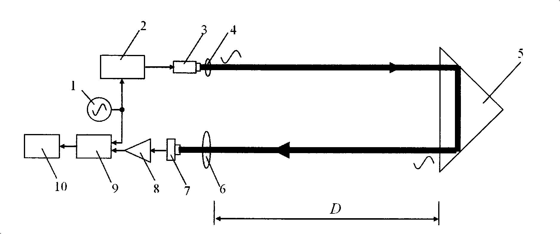
[0004] The main disadvantage of the phase method laser ranging using the above measurement scheme is that the attenuation form of the intensity of the returned light signal is the fourth power attenuation function of the measured distance. With the increase of the measured distance, the returned light signal attenuates quickly, resulting in The noise ratio decreases, which limits the improvement of the measurement range
Although the energy of the returned light can be improved by increasing the output power and modulation degree of the laser, the effect on increasing the measurement range is not obvious because the power of the continuous output laser cannot be greatly increased; increasing the aperture of the receiving optical system and The reflective area of ​​the retroreflector can also increase the energy of the returned light, but this will cause the volume of the instrument to increase rapidly with the increase in the measurement range requirements

Method used


Image

  • Active collaboration type phase laser distance measuring method and apparatus
  • Active collaboration type phase laser distance measuring method and apparatus
  • Active collaboration type phase laser distance measuring method and apparatus

Examples


Embodiment Construction

[0025] Embodiments of the present invention will be described in detail below in conjunction with the accompanying drawings.

[0026] Active cooperative phase laser ranging method:

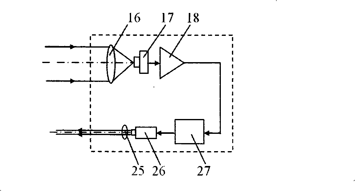
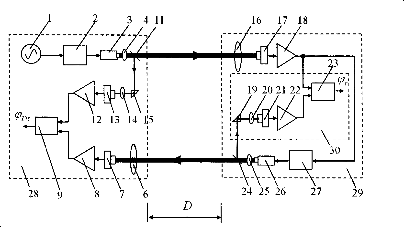
[0027] figure 2 A schematic diagram of the active cooperative target proposed by the present invention is given. The function of the active cooperative target device 29 is to actively amplify the laser signal from the measurement device 28 and return it along the original path. It is mainly composed of converging lens C16, avalanche photodetector C17, photoelectric conversion circuit C18, laser intensity modulation unit B27, laser B26, and laser beam shaping mirror group B25. During measurement, the laser signal from the measurement end is converged by the receiving and converging lens C16 to the photosensitive surface of the avalanche photodetector C17, and then converted into an electrical signal by the photoelectric conversion circuit C18, and the electrical signal is modulated by the laser i...


PUM


Abstract

The invention belongs to the laser ranging technical field, which arranges an active cooperation target end device at an object in a laser ranging process, wherein the active cooperation target device amplifies and reflects the laser signal of a ranging end to the ranging end, the ranging end receives the optical signal from the active cooperation target end device to realize the cooperation between the active cooperation target end device and the ranging end to complete the ranging process. The invention changes the prior single beam roundtrip measurement mode into a double beam single-pass cooperation measurement method to change the attenuation mode of the reflected light energy of the measurement system from the fourth power attenuation function of the ranged distance in the prior art to second power attenuation function, thereby improving the reflected light energy and the signal noise ratio of the system, improving ranging effect along with the increase of distance and realizing remote high accuracy measurement under low laser emission power and optical receiving aperture. The inventive device is composed of a ranging end device and an active cooperation end device having same optical and electric structures with the ranging end device.

Description

technical field [0001] The invention belongs to the technical field of laser ranging, in particular to an active cooperative phase laser ranging method and device. Background technique [0002] Laser ranging is a comprehensive technology that integrates various technologies such as optics, laser, optoelectronics and integrated electronics. Semiconductor laser ranging devices are widely used in military, aerospace, robot vision, industrial automatic production lines and other fields due to their advantages of non-contact, high precision, small size, low cost, and long service life. For absolute distance measurement, the commonly used laser ranging methods are pulse method and phase method. The pulse method has the advantages of wide measurement range and is suitable for non-cooperative targets, but its measurement accuracy is low. The distance measuring device using a pulsed semiconductor laser can measure up to several kilometers, and the accuracy is generally 0.1 to 1m. ...

Claims


Application Information

Patent Timeline
Patent Type & Authority Applications(China)
IPC IPC(8): G01S17/08
Inventor 谭久彬刘思远胡鹏程张培
Owner HARBIN INST OF TECH
Learn More