Sonic surface wave pressure sensor using composite mold

A technology of pressure sensor and surface acoustic wave, which is applied in the measurement of fluid pressure using piezoelectric devices, the measurement of the property force of piezoelectric devices, and the measurement of fluid pressure. Physical position consistency problem, poor stress concentration effect, damage to pressure sensor and other problems, to achieve the effect of improving long-term stability, good accuracy and reducing temperature gradient

Active Publication Date: 2009-01-28
SHANGHAI JIAO TONG UNIV
View PDF5 Cites 21 Cited by
  • Summary
  • Abstract
  • Description
  • Claims
  • Application Information

AI Technical Summary

Problems solved by technology

[0008] The Chinese patent with the patent publication number CN1619954 proposes an improvement measure, but its installation process still does not completely solve the problem of consistency between the protrusion of the packaging box and the physical position of the active chip
Apparently this mechanism can sometimes damage the pressure sensor
In addition, the cross-sectional area of ​​this kind of protrusion is large, that is, the sharpening of the end is not good, and its s...

Method used


Image

  • Sonic surface wave pressure sensor using composite mold
  • Sonic surface wave pressure sensor using composite mold
  • Sonic surface wave pressure sensor using composite mold

Examples


Embodiment 1

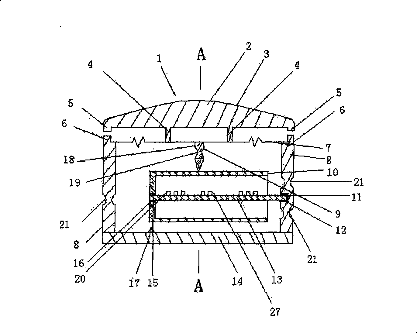
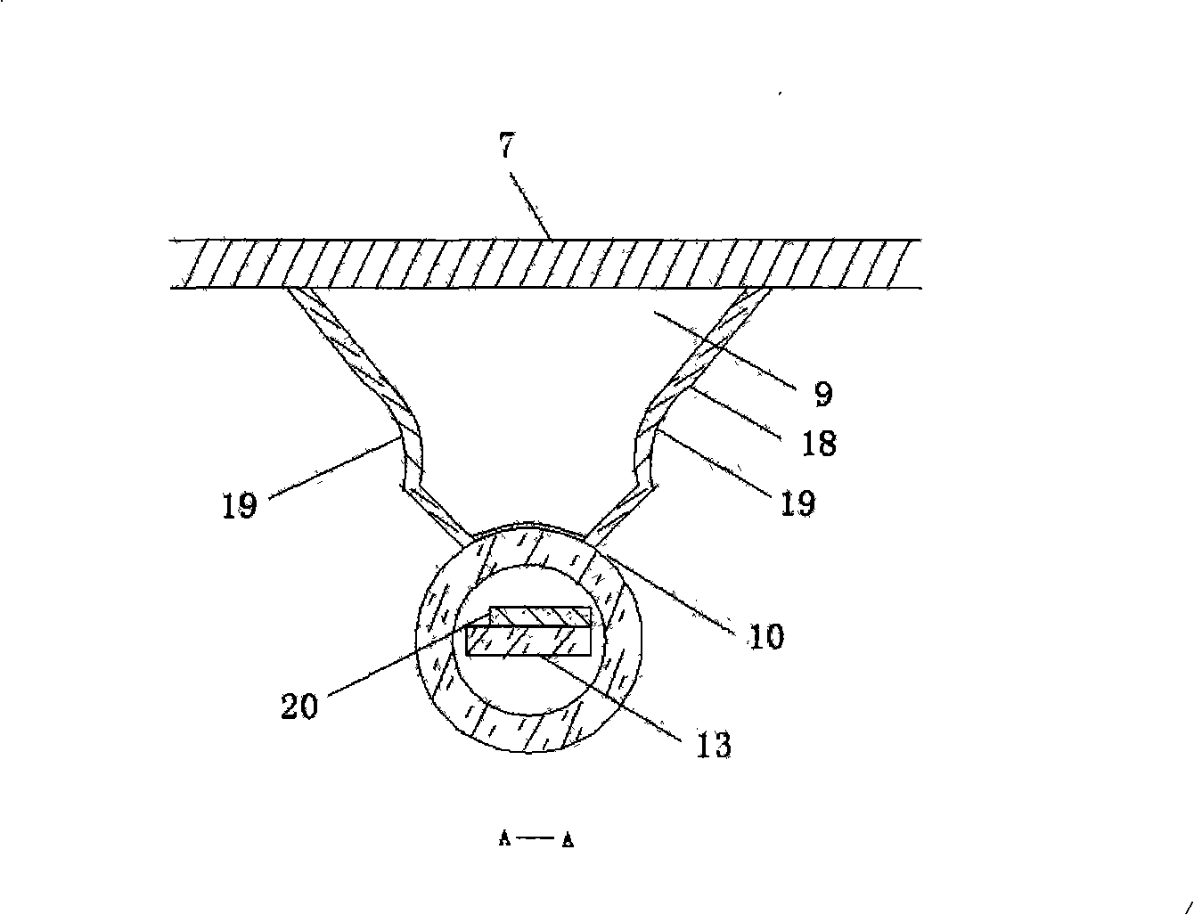
[0046] Such as figure 1 , figure 2 , image 3 As shown, this embodiment includes: mushroom-shaped pressurized cap 2, metal force guide column 4, hard spherical shell pressure guide metal diaphragm 7, metal shell side wall 8, force guide thimble piece 9, force guide cylinder 10, quartz The cantilever beam type sensitive element 13, the bottom shell 14, and the overvoltage protection device 17, wherein: the hard-core spherical shell pressure-guiding metal diaphragm 7, the metal shell side wall 8, and the bottom shell 14 form an airtight container, and the hard-core spherical shell The upper surface of the pressure-guiding metal diaphragm 7 is connected to the mushroom-shaped pressure cap 2 through the metal force-guiding column 4, and the lower surface is fixed with a force-guiding thimble 9, which is rigidly connected with the force-guiding cylinder 10, and the force-guiding cylinder 10 There is a quartz cantilever beam sensitive element 13 inside. One end of the quartz cant...

Embodiment 2

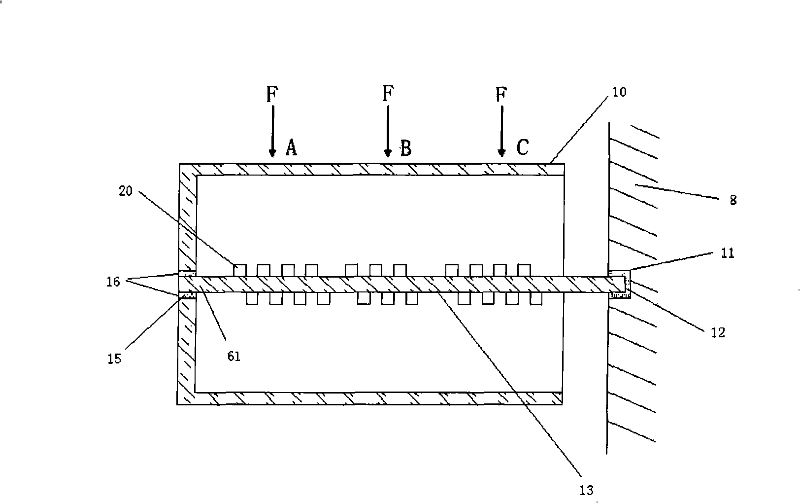
[0064] Such as Image 6 As shown, the structure difference between this embodiment and Embodiment 1 is that the Rayleigh wave mode SAW device 20 is arranged on the upper surface of the piezoelectric quartz wafer 21, and the surface-grazing body wave SSBW device 27 is arranged on the piezoelectric quartz wafer 21. On the lower surface, the propagation direction of the surface acoustic wave forms an angle of 50° with the X-axis of the wafer, and the propagation direction of the grazing body wave 35 excited by the SSBW device 27 and the Rayleigh wave 34 excited by the Rayleigh wave mode SAW device 20 form an angle of 90° . The Rayleigh wave mode SAW device 20 is responsible for measuring temperature, and the skimming body wave SSBW device 27 is responsible for measuring pressure.

[0065] Obviously, the second embodiment adopts the combination of the Rayleigh wave mode SAW device 20 and the skimming body wave SSBW device 27 to realize the measurement of pressure and temperature ...

Embodiment 3

[0067] Such as Figure 7 As shown, the structure difference between the present embodiment and the first embodiment is that the Rayleigh wave mode SAW device 20 consists of an interdigital transducer 25 and three second reflection grids 35, 36 and 37 (or more than three) Arranged in a row to form a reflective delay line (label) structure, the SSBW device 27 is composed of a second interdigital transducer 28 and two third reflective grids. The Rayleigh wave mode SAW device 20 is arranged on the upper surface of the piezoelectric quartz wafer 61, and the surface-grazing body wave SSBW device 27 is arranged on the lower surface of the piezoelectric quartz wafer 61, and both have different depths of energy distribution on the piezoelectric quartz wafer 61, Through their three-dimensional intersection, the measurement of pressure and temperature is realized.


PUM

PropertyMeasurementUnit
Lengthaaaaaaaaaa
Lengthaaaaaaaaaa

Abstract

The invention relates to a surface acoustic wave pressure sensor adopting a compound die, which pertains to the technical field of sensors and comprises a mushroom pressurization cap, a hard-core ball shell pressure guiding metal diaphragm, a metal force guiding column, an overvoltage protective device, a metal shell side wall, a force guiding ejector disk, a force guiding cylinder, a quartz cantilever beam sensitive element, a bottom case and an overvoltage protective device, wherein, the hard-core ball shell pressure guiding metal diaphragm, the metal shell side wall and the bottom case form an air-tight container; the upper surface of the hard-core ball shell pressure guiding metal diaphragm is connected with the mushroom pressurization cap by the metal force guiding column, while the lower surface thereof is fixed with the force guiding ejector disk rigidly connected with the force guiding cylinder; the interior of the force guiding cylinder is provided with the quartz cantilever beam sensitive element; one end of the quartz cantilever beam sensitive element is connected with a blind hole end surface of the force guiding cylinder by glass powder, while the other end thereof is connected with a blind hole of the metal shell side wall by utilizing glass powder. The flexibility of the invention is 15 times higher than the conventional surface wave sensor, and the surface acoustic wave pressure sensor of the invention is suitable for the wireless monitoring of the tire pressure of carts.

Description

technical field [0001] The invention relates to a pressure sensor in the technical field of sensors, in particular to a surface acoustic wave pressure sensor using a composite mold. Background technique [0002] The "smart tire" that monitors tire pressure, temperature and other parameters in real time can give early warning of tire burst and avoid accidental disasters. At the same time, it can effectively improve the maneuverability of the vehicle, save fuel, extend the service life of the tire and improve the safety comfort. With the legislation in the United States and Europe, "smart tires" have been widely valued by countries all over the world and have broad application prospects. It is a new product with a large quantity and a wide range, a huge market and a potential market, and considerable economic benefits. As we all know, the automotive tire pressure sensor has high requirements on the technical indicators of the product, but it requires low cost. In other word...

Claims


Application Information

Patent Timeline
IPC IPC(8): G01L9/08G01L1/16G01L19/00
Inventor 韩韬林江
Owner SHANGHAI JIAO TONG UNIV
Why Eureka
Try Eureka