
Adiabatic calorimeter and heat measuring system

An adiabatic heat and calorimeter technology is applied in the field of material heat capacity measuring instruments, which can solve the problems of large temperature variability, large volume, and difficulty in measuring substances with small acquisition amounts, so as to improve stability and accuracy, The device has compact structure and stable performance

Active Publication Date: 2009-01-28
DALIAN INST OF CHEM PHYSICS CHINESE ACAD OF SCI
View PDF0 Cites 36 Cited by
  • Summary
  • Abstract
  • Description
  • Claims
  • Application Information

AI Technical Summary

Problems solved by technology

Most domestic adiabatic calorimeters [Document 8. Zhang Jintao, Yuan Zundong, Qiu Ping, Duan Yuning, Sun Jianping. High-precision automatic adiabatic calorimeter. Acta Metrology, 2005(26): 320-325. Document 9. ZhaoXiaoming, Liu Zhigang and Chen Zhongqi.J.Chem.Eng.Data, 2006(51):867-870. Literature 10. Yang C.G., Xu L., Zhang L.Q., Chen N..Energy Conversion and Management, 2006(47):1124- 1132.] The sample container volume is relatively large, and the precision and accuracy of the heat capacity test are low, specifically:
[0003] 1) The volume of the sample container is mostly about 60ml, and it is difficult to measure some substances with a small amount of acquisition
[0004] 2) The temperature variation during the equilibrium period of the heat capacity test is relatively large, generally ±5mK
[0005] 3) The precision of the heat capacity test is low, generally ±0.3%
[0006] 4) The accuracy of the heat capacity test is low, generally ±0.5%
[0007] 5) The instrument has a low degree of automation

Method used


Image

  • Adiabatic calorimeter and heat measuring system
  • Adiabatic calorimeter and heat measuring system
  • Adiabatic calorimeter and heat measuring system

Examples


Embodiment Construction

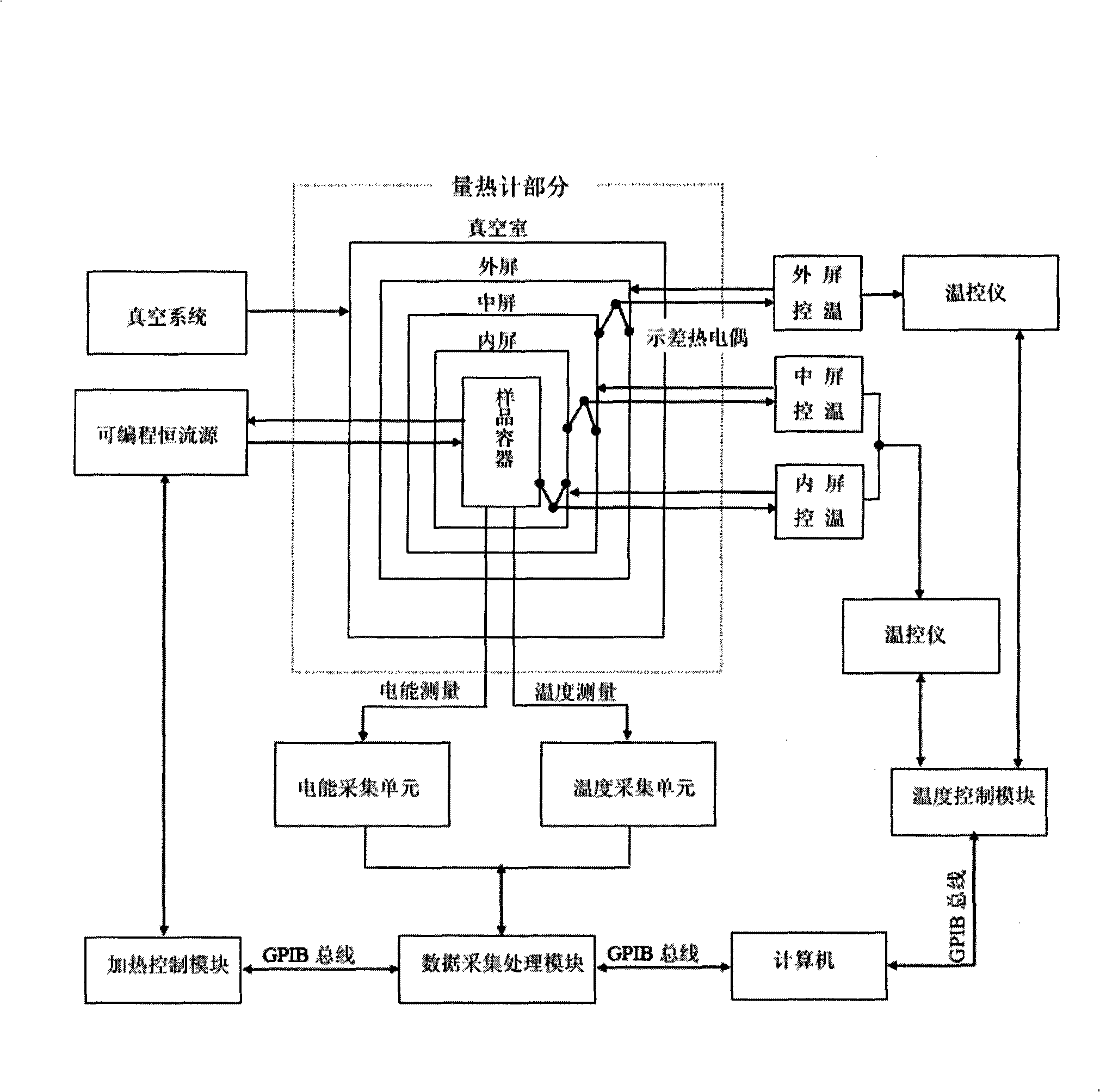
[0031] The invention not only includes the calorimeter and the calorimetric system, but also includes the software control principle and process of the calorimetric system.

[0032] 1. Calorimeter

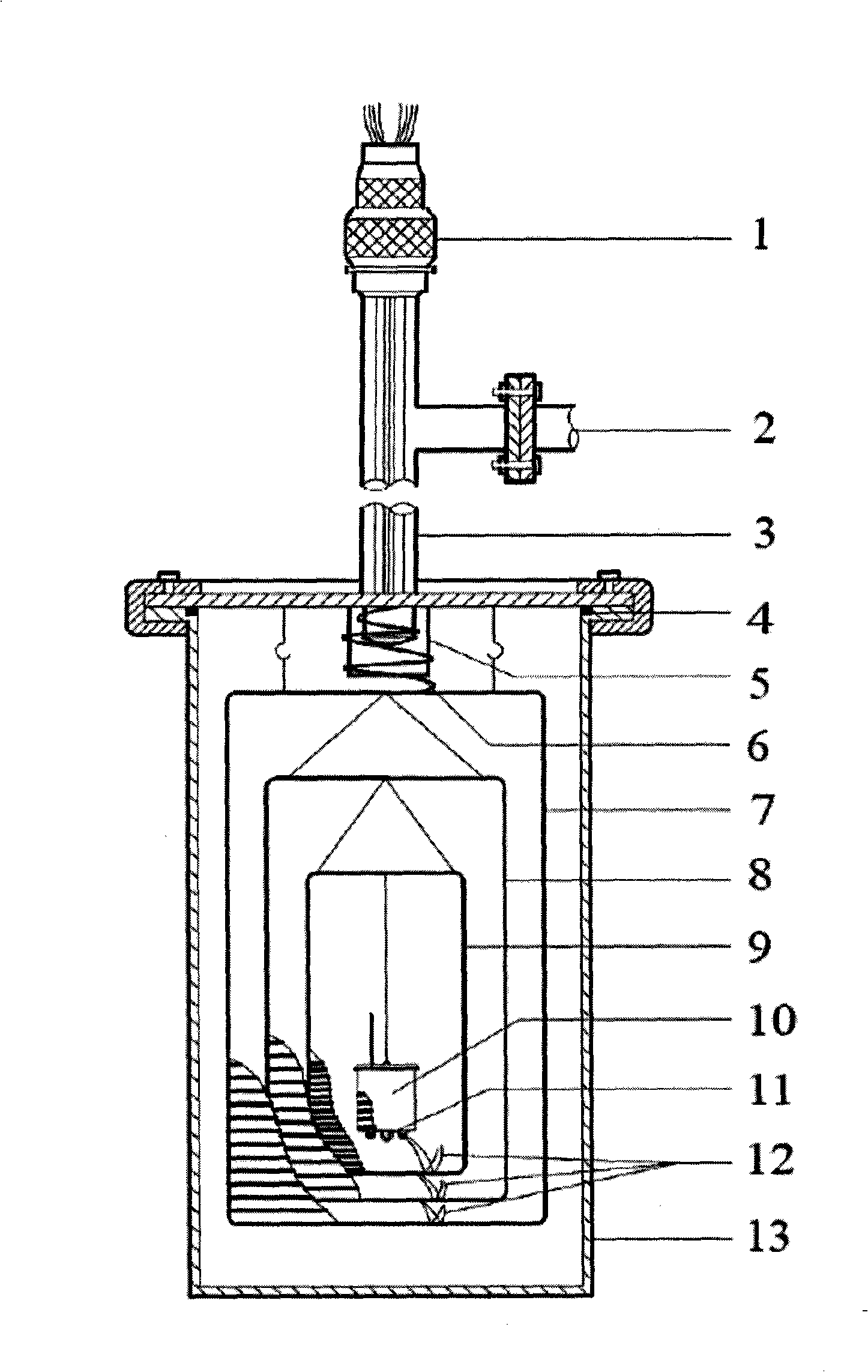
[0033] An adiabatic calorimeter, such as figure 1 shown. The calorimeter adopts three-layer insulation screen temperature control, including vacuum sealing connector 1, vacuum system valve 2, vacuum conduit 3, sealing gasket 4, wire temperature control ring 5, wire bundle 6, outer insulation screen 7, middle insulation screen 8. Inner thermal insulation screen 9, sample container 10, thermometer and thermocouple socket 11, differential thermocouple 12 and vacuum chamber 13.

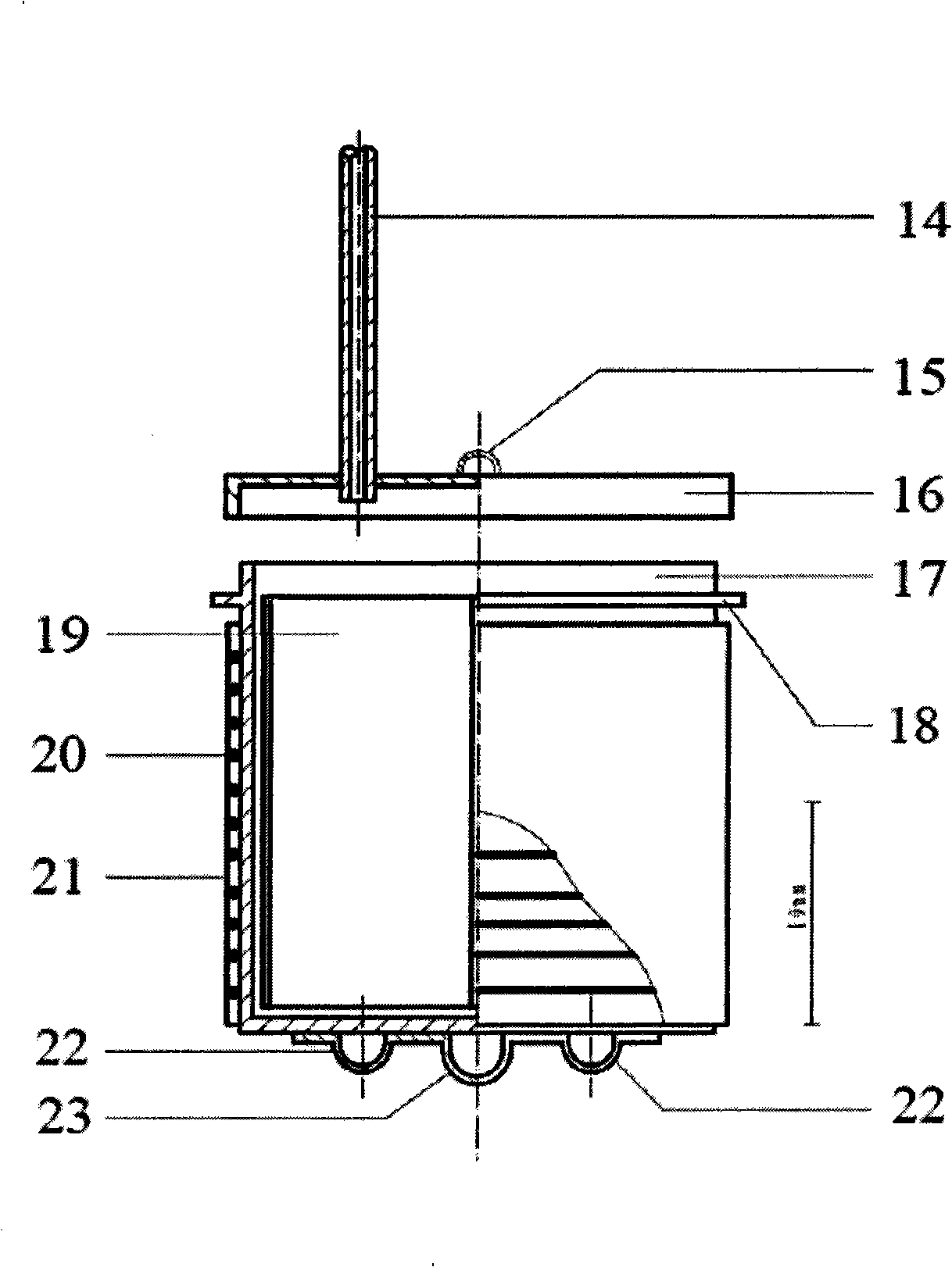
[0034]The vacuum chamber 13 is a closed cylinder with an upper cover; the outer heat insulation shield 7, the middle heat insulation shield 8 and the inner heat insulation shield 9 are all cylindrical structures, which are composed of an upper cover, a cylinder body and a lower cover. There is a detachable ...


PUM


Abstract

The invention relates to a substance heat capacity measuring instrument, in particular to an adiabatic calorimeter and a calorimetric system thereof, and comprises a vacuum sealed socket connector, a vacuum system valve, a vacuum conduit, a temperature control ring of conducting wires, a conducting wire beam, an outer heat screen, a middle heat screen, an inner heat screens, a sample container, a differential thermocouple and a vacuum chamber. The substance heat capacity measuring instrument has compact structure, stable performance and convenient operation, realizes the adiabatic calorimetric experiment, which comprises a whole automatically controlled and finished process of electricity energy importing, heat insulation controlling, temperature measuring, heat equilibrium judging, heat capacity data computing and processing, and result displaying and printing and the like. Through the detection with a standard calorimetric substance Alpha-Al2O3 and the comparison with internationally acknowledged data that is published by National Institute of Standards and Technology (NIST), the measuring heat capacity variability of variation with temperature of the instrument is certificated to be plus or minus 0.2mK per minute<-1>, the precision of the instrument is certificated to be plus or minus 0.12 percent and the accuracy of the instrument is certificated to be plus or minus 0.14 percent.

Description

technical field [0001] The invention relates to a material heat capacity measuring instrument, in particular to an adiabatic calorimeter for measuring material heat capacity and the establishment of a calorimetric system thereof. Background technique [0002] Heat capacity is one of the important basic thermodynamic data of matter, and it is of great significance to many theoretical studies of physics and chemistry and engineering technology design related to energy and materials. Adiabatic calorimetry is the most reliable experimental method for obtaining material heat capacity and thermodynamic data. Therefore, at present, a lot of work has been done on the research of using adiabatic calorimetry devices to measure material heat capacity [Document 1. Sun Yi, TanZhicheng, Yin Anxue, et al.Acta Metrologica Sinica, 1982, 3(4): 301-307. Literature 2. Tan Zhicheng, Zhou Lixing, Cheng Shuxia, et al.Scientia Sinica, Ser.B, 1983, 26(10): 1014 -1026. Literature 3. Yin Anxue, Wenbi...

Claims


Application Information

Patent Timeline
IPC IPC(8): G01N25/20G01N25/00
Inventor 谭志诚史全邸友莹张洪涛
Owner DALIAN INST OF CHEM PHYSICS CHINESE ACAD OF SCI
Learn More