Permanent magnetism magnetic pole component for high-power permanent magnet motor

A technology for permanent magnet motors and permanent magnet generators, which is applied in the directions of permanent magnets, magnetic circuit rotating parts, magnetic circuit shape/style/structure, etc. It can solve the problems of magnetic pole assembly difficulty, cumbersome assembly process, and temperature rise, etc., to achieve Simple and stable magnetic pole interlocking fixed structure, improved corrosion resistance, and easy industrial production

Active Publication Date: 2009-01-28
BEIJING ZHONG KE SAN HUAN HI TECH
View PDF1 Cites 6 Cited by
  • Summary
  • Abstract
  • Description
  • Claims
  • Application Information

AI Technical Summary

Problems solved by technology

With the increase of the power of the permanent magnet motor, the area and volume of the single magnetic pole increase accordingly. In addition, the operating environment of the high-power permanent magnet motor is relatively harsh, the temperature rises, and the heat dissipation is large. Corrosion, heat resistance and demagnetization are particularly important. Traditional magnetic pole surface protection methods often cannot meet anti-corrosion requirements; The chance of scratches on the surface of the magnet is greatly increased. Once the surface is damaged, it will directly threaten the performance of the NdFeB magnet and the service life of the motor
After the well-known motor rotor magnetic steel is assembled, the surrounding epoxy

Method used


Image

  • Permanent magnetism magnetic pole component for high-power permanent magnet motor
  • Permanent magnetism magnetic pole component for high-power permanent magnet motor
  • Permanent magnetism magnetic pole component for high-power permanent magnet motor

Examples


Embodiment 1

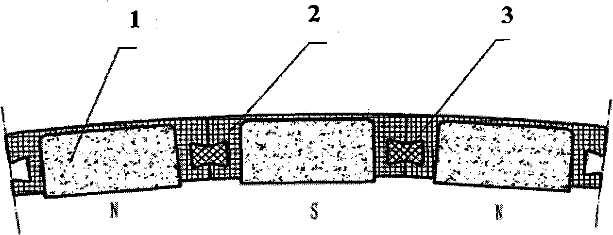
[0041] Figure 5 It is a partial view of the stator and rotor of a 2MW direct-drive permanent magnet wind turbine, the inner rotor structure, AC voltage: 690V, speed: 20rpm, multi-pole fractional slot winding, and the magnetic pole form is the same as figure 1 Similarity: the width of permanent magnet 1 is 50mm, and the axial length of permanent magnet 1 is 1200mm. The magnet protection positioning cover 2 is injection-molded as a whole. After magnetization, it is bonded and fixed with the rotor magnet yoke 4 of the motor with epoxy resin adhesive. The radial N and S magnetic poles are alternately arranged on the rotor magnet yoke 4. Splicing of the same polarity, after the adjacent magnetic poles are bonded, the magnetic poles are locked by injection-molded double dovetail-shaped magnetic pole locking pins 3 (with epoxy resin adhesive), and the magnet protection positioning cover 2 and magnetic pole locking pin 3 The material is heat-resistant insulating material-PPS (polyph...

Embodiment 2

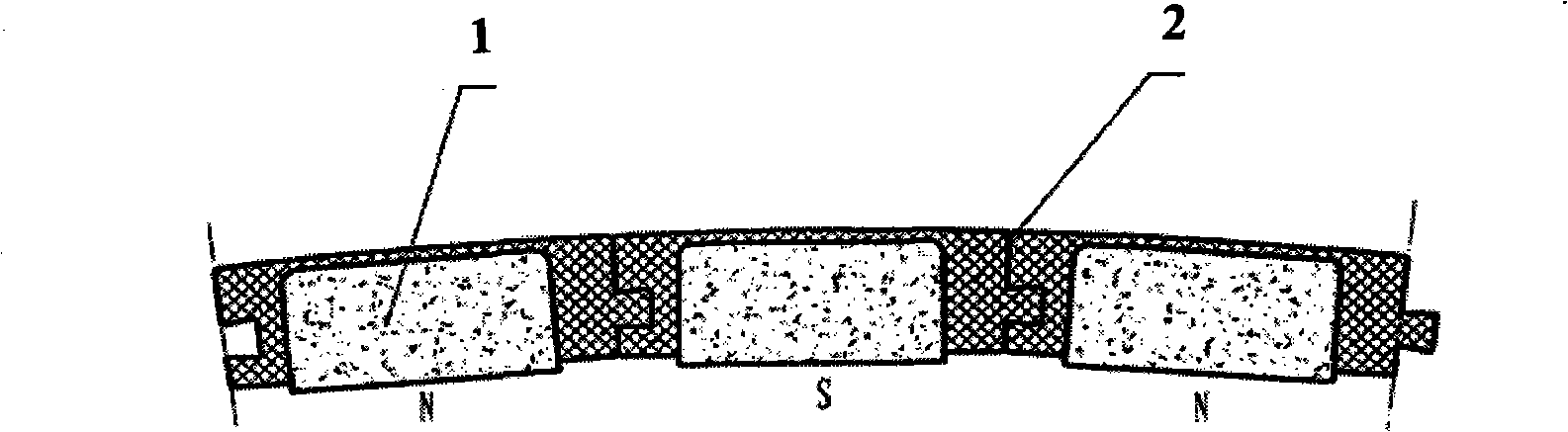
[0043] Figure 6 It is a partial view of the stator and rotor of a 3MW direct-drive permanent magnet wind turbine, the outer rotor structure, AC voltage: 690V, speed: 19rpm, multi-pole fractional slot winding, and the magnetic pole form is the same as figure 2 Similar, the width of permanent magnet 1 is 65mm, and the axial length of permanent magnet 1 is 1000mm. The injection-molded magnet protection positioning cover 2 is bonded as a whole with epoxy resin glue, and after magnetization, the epoxy resin adhesive is used to bond and fix the motor rotor magnet yoke 4, and the radial N and S magnetic poles are alternately arranged on the rotor On the magnet guide yoke 4, the axial direction is spliced ​​with the same polarity. After the adjacent magnetic poles are bonded, the magnetic poles are locked by injection-molded circular magnetic pole locking pins 3 (add epoxy resin adhesive) and the positioning cover is protected by the magnet. 2 and the magnetic pole locking pin 3 ar...

Embodiment 3

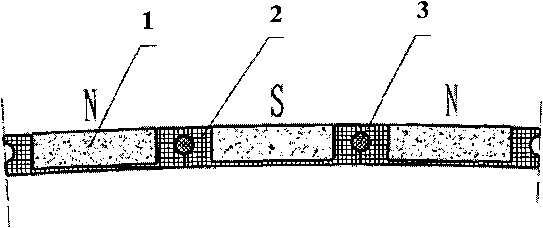
[0045] Figure 7 Partial view of the stator and rotor of the permanent magnet linear motor used for sorting and transmission in the post and telecommunications system, driving voltage: 100V, maximum speed: 3m / sec, multi-pole fractional slot winding, magnetic pole form and image 3Similarly, the width of permanent magnet 1 is 30mm, the length of permanent magnet 1 (axial direction) is 100mm, and the stator (when the linear motor is working, the magnetic pole part is still, called the stator), the permanent magnet 1 is composed of a single piece (10×30×98mm) of neodymium iron The boron permanent magnet block is composed of a single NdFeB permanent magnet block and the injection-molded magnet protection positioning cover 2 bonded together with epoxy resin glue, and the epoxy resin adhesive is used to connect the motor stator magnet guide yoke 4 after magnetization Bonding and fixing, the N and S magnetic poles in the length direction of the motor stator are alternately arranged o...


PUM


Abstract

The invention relates to a permanent-magnet magnetic pole component for a high-power permanent-magnet motor, comprising permanent magnets, a magnetic conduction yoke of a rotor, magnet protection positioning covers and magnetic pole locking pins, wherein the permanent magnets, the magnetic conduction yoke of the rotor and the magnet protection positioning covers form a permanent-magnet magnetic pole through adhesion, the arrangement of alternate N and S pole permanent-magnet magnetic poles is formed on the magnetic conduction yoke of the rotor, and two or a plurality of permanent-magnet magnetic poles are mutually connected to form the permanent-magnet magnetic pole component. The permanent-magnet magnetic pole component realizes the corrosion resistance and the thermal insulation of neodymium-iron-boron magnets, and greatly prolongs the service life of the permanent magnets.

Description

technical field [0001] The invention belongs to the technical field of permanent magnet motors, in particular, the invention relates to permanent magnet pole assemblies in high-power permanent magnet motors. Background technique [0002] In the past ten years, with the continuous improvement of the performance of NdFeB permanent magnet materials, the improvement of thermal stability and corrosion resistance of materials and the gradual reduction of prices, the development and application of high-power NdFeB permanent magnet motors have entered a new stage. stage. [0003] Due to the relatively small volume of the magnets used in traditional low-power permanent magnet motors, the surface of the magnets can usually meet the requirements of the motor after anti-corrosion treatment such as electroplating and electrophoretic coating. With the increase of the power of the permanent magnet motor, the area and volume of the single magnetic pole increase accordingly. In addition, th...

Claims


Application Information

Patent Timeline
IPC IPC(8): H02K15/03H02K1/27H01F7/02
Inventor 王玉国贾敬东
Owner BEIJING ZHONG KE SAN HUAN HI TECH
Why Eureka
Try Eureka