Die grid for producing composite block and casting forming method of composite block

A composite block and formwork technology, which is applied in the direction of ceramic forming machines, molds, manufacturing tools, etc., can solve the problems of less block layers, high production costs, and loss of strength, and achieve low overall cost, short construction period, dry down effect

Inactive Publication Date: 2009-02-04
高学保
View PDF0 Cites 6 Cited by
  • Summary
  • Abstract
  • Description
  • Claims
  • Application Information

AI Technical Summary

Problems solved by technology

It adopts the integral pouring process of single-cavity mold, and the block matrix is ​​continuous foam concrete material. There are still problems such as less block layers, strength loss, water seepage and thermal bridge caused by matrix cracking, and there are complex processes and production problems. Disadvantages such as high cost
In order to solve the above problems, the applicant previously proposed the concept of multi-layer composite block and filed a patent application, but there is still no feasible solution for what kind of equipment and process to use for production

Method used


Image

  • Die grid for producing composite block and casting forming method of composite block
  • Die grid for producing composite block and casting forming method of composite block
  • Die grid for producing composite block and casting forming method of composite block

Examples


Embodiment 1

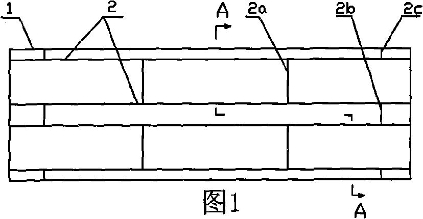
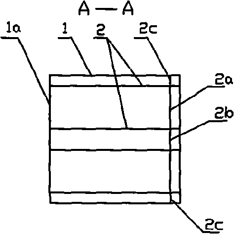
[0034] Embodiment one: the mold frame basic form that the present invention provides is as shown in Figure 1, figure 2 As shown, it includes a rectangular peripheral frame 1 and a frame bottom 1a that is movably connected and matched. At least one pair of partition plates 2 (2 pairs in this example) are arranged in the peripheral frame 1, and each pair of partition plates 2 is provided with The connection plate 2a is also provided with a connection plate 2b between every two pairs of partition plates 2, and a positioning plate 2c is provided near the part of the outer frame, so that all the partition plates, connection plates, and positioning plates are integrated, and formed with the peripheral frame. Active fit that can be inserted or removed. Such as figure 2 As shown, all connecting plates and positioning plates can only be arranged on a small section above, and cannot affect the circulation of the cavity below.

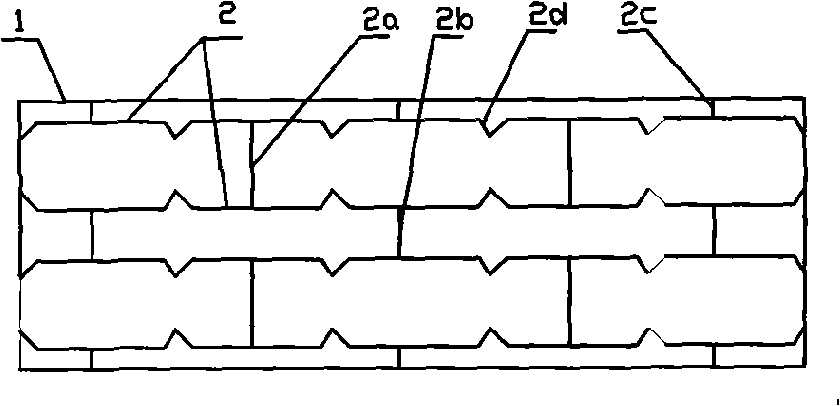
[0035] Such as image 3 Shown, in order to demarcate the...

Embodiment 2

[0036] Embodiment two: if Figure 5 shown in image 3 On the basis of the mold frame shown, a pair of inner partitions 4 are arranged between each pair of partition plates 2, and each inner partition 4 is in the division range of the corresponding V-shaped groove mark, and the connecting plates 2e and Splitter board 2 connection.

[0037] Such as Image 6 As shown, one can go further, in Figure 5 On the basis of each pair of inner partitions, an inner frame 5 is connected.

[0038] It can be seen from the pouring mold frame described in Embodiment 1 and Embodiment 2 that the partition plate, inner partition board, and inner frame set in the peripheral frame can also have other combinations, and its essence is to divide the inside of the peripheral frame into different parts. Each section can be poured with different block forming materials.

Embodiment 3

[0039] Embodiment three: adopt pouring mold frame shown in Fig. 8, it is in Figure 5 It is changed on the basis of the pouring formwork shown, that is, four pairs of dividing plates 2 are arranged in the outer frame 2, and a polystyrene foam board 9 is respectively placed between each pair of inner dividing plates 4, and it is close to the inner dividing plate. 4 The hypotenuses 4a at both ends are positioned. As shown in Fig. 9, a layer of rubber pad 1b is compounded on the frame bottom 1a of the peripheral frame 1, and its effect is that when the peripheral frame 1 is demoulded, the cast blocks are easily separated from the rubber pad.

[0040] The mold frame shown in Fig. 8 has formed the pouring area of ​​three kinds of materials, namely between the dividing plate 2 and the peripheral frame 1 and the zone 12 between every pair of dividing plates 2 between every pair of dividing plates, dividing plate 4 and poly The area 11 between the benzene foam boards 9. Such as Fi...


PUM


Abstract

The invention relates to a bolster for making composite blocks and is characterized in that the bolster comprises a rectangular outer surrounding frame (1), separation boards (2) are arranged in the outer surrounding frame (1), and an internal surrounding frame (5) is arranged between the separation boards (2). The invention also relates to a method for moulding the composite blocks by casting, and the following steps are adopted: 1. a foam board (3) is arranged in the internal surrounding frame (5); 2. foam concrete and hadite foam concrete are cast among the outer surrounding frame (1), the separation boards (2) and the internal surrounding frame (5); after finishing the casting, all the separation boards and the internal clapboards are taken out, and various cast materials are facilitated to fuse each other; 4. after the various materials become dry, demoulding is carried out; 5. six-side cutting is carried out on the dry blocks. The advantages of the invention are that: making composite block bolsters is simple, the method for manufacturing the composite blocks is simple, and the manufactured composite blocks have the advantages of light mass, high stiffness, low water absorption rate, small drying shrinkage and good hot work ability.

Description

technical field [0001] The invention belongs to the production mold frame of composite block in the building wall masonry system, in particular to a mold frame for producing multi-layer composite block and a pouring molding method of the composite block. Background technique [0002] Building energy conservation is a basic national policy for developing a conservation-oriented society and sustainable development. Guided by the implementation of the building energy saving standard of 50% and the policy of achieving building energy saving of 65%, a large number of energy-saving thermal insulation blocks are constantly appearing. After searching, in the past few years, there is a kind of composite thermal insulation that fills the holes of the blocks with foam boards or pouring foam particles. Blocks, all the materials of the above thermal insulation blocks are single, and the blocks formed have fewer layers, and there are some problems such as high water absorption, large dryi...

Claims


Application Information

Patent Timeline
Patent Type & Authority Applications(China)
IPC IPC(8): B28B7/22B28B7/24B28B23/00
Inventor 高学保
Owner 高学保
Why Eureka
Try Eureka