Method for utilizing flue gas low-temperature heat quantity for industrial furnace

An industrial furnace and flue gas technology, applied in air heaters, furnaces, waste heat treatment, etc., can solve problems such as high operating costs, complex processes, and unutilized heat, to improve thermal efficiency, increase temperature, and improve the average temperature field. The effect of heat intensity

Inactive Publication Date: 2009-02-04
江阴市和荣燃烧设备有限公司
View PDF0 Cites 12 Cited by
  • Summary
  • Abstract
  • Description
  • Claims
  • Application Information

AI Technical Summary

Problems solved by technology

[0004] The temperature of the flue gas discharged from the oil refining tubular heating furnace must be strictly controlled above the dew point. Generally, the exhaust gas temperature is around 200°C. It can be seen that the heat below 200°C in the flue gas is not used, and there is also CO 2 , SO x , NO x and other acidic pollutant gases are discharged into the atmosphere, causing serious environmental pollution
[0005] In order to meet the requirements of environmental protection emission standards, many enterprises currently use low-sulfur fuel oil and / or adopt flue gas desulfurization technology, which is difficult to apply due to its large investment, high operating costs, large footprint, and complicated processes

Method used


Image

  • Method for utilizing flue gas low-temperature heat quantity for industrial furnace

Examples


Embodiment Construction

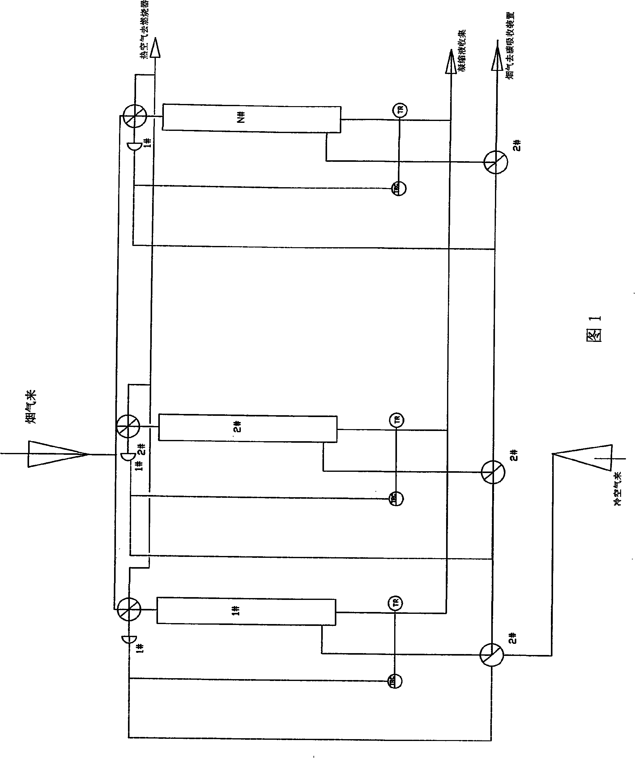
[0013] Referring to Fig. 1, the method for utilizing the low-temperature heat of industrial furnace flue gas according to the present invention is to use three or more groups of regenerative air preheaters connected in parallel, and the regenerative air preheaters are made of ceramic or glass-lined or The air preheater in which the ceramic matrix composite material is the wall and the ceramic regenerator is the heat transfer element, the method specifically includes the following process: the flue gas above the dew point from the convection section of the heating furnace flows to the first group of regenerative The 1# three-way valve of the air preheater enters the first group of regenerative air preheater through the 1# three-way valve, and the flue gas passes through the heat to the heat storage body of the first group of regenerative air preheater And cool down to below 70 ℃, through the 2# three-way valve of the first group of regenerative air preheater, it flows into the f...


PUM


Abstract

The present invention relates to a method for utilizing the low-temperature heat of the smoke of the industry furnace; three groups or more of the heat accumulation air pre-heaters are connected to each other in parallelism. The present invention adopts the process that the smoke that is from the counter-flow section of the heating furnace and is higher than the dew point flows to a first group of heat accumulation air pre-heater; after the heat is transferred to a heat accumulation body of a first group of heat accumulation air pre-heater, the temperature of the smoke is reduced to 70 DEG C or less, and is discharged to the chimney; during the temperature reduction process, a condensed fluid is precipitated; the condensed fluid is discharged into a collection pipeline through an automatic liquid sealing device valve to be collected; the air flows to the heat accumulation air pre-heater that accumulates the heat; at the same time, the heat accumulation body in the heat accumulation air pre-heater transfers the accumulated heat to the air, and the produced high-temperature air flows to the combustor to be combusted at a high temperature; when three groups or more of the heat accumulation air pre-heater are connected with each other in parallelism, the air flows to the next group of the heat accumulation air pre-heater to perform the same heat exchanging process; the paralleling-connected three groups or more of the air pre-heaters are automatically switched, so as to realize the automatic control. The dew point is used to condense the acid gas in the smoke, thereby realizing the dual functions of energy conservation and environmental protection.

Description

(1) Technical field [0001] The invention relates to a method for utilizing low-temperature heat from flue gas of an industrial furnace, in particular to utilization of low-temperature heat at a temperature below the dew point of flue gas. It belongs to the technical field of petrochemical equipment. (2) Background technology [0002] With the rapid growth of the economy, great achievements have been made in various constructions, but at the same time, huge resources and environmental costs have been paid. The contradiction between economic development and resources and environment has become increasingly acute, and the environmental pollution problem has responded strongly. This is directly related to the unreasonable economic structure and the extensive growth mode. The emission of polluting gases causes the global climate to be harsh. According to the survey, the acidity of seawater in the west coast of North America increased in 2007. The acidic seawater found in the wa...

Claims


Application Information

Patent Timeline
Patent Type & Authority Applications(China)
IPC IPC(8): F24H8/00F27D17/00F28D20/00
CPCY02B30/102Y02E60/142Y02B30/00Y02E60/14
Inventor 葛京鹏周国华陶革新贡程红明晓先仇晓东季科敏卢康杨卫
Owner 江阴市和荣燃烧设备有限公司
Why Eureka
Try Eureka