Retaining structure of cement-soil pile-wall for rail beam and construction method

A technology for cement-soil piles and supporting structures, which is used in foundation structure engineering, sheet pile walls, excavation, etc., can solve the problems of increasing the diameter of the stirring pile, increasing the pulling resistance, and troublesome support and dismantling, and achieves high bending resistance. The effect of strength and stiffness, reduction of extraction stress, and easy and convenient extraction

Inactive Publication Date: 2009-02-11
袁建标
View PDF0 Cites 3 Cited by
  • Summary
  • Abstract
  • Description
  • Claims
  • Application Information

AI Technical Summary

Problems solved by technology

[0003] To a certain extent, the SMW construction method can recycle the H-shaped steel in the construction method and save engineering investment. However, it is restricted by the soil conditions of the site, the mixing method, and the bending stiffness and strength of the H-shaped steel itself. The depth of pit support is often limited. According to the existing domestic construction performance, the depth of foundation pit support is generally not more than 13m. The diameter of the large mixing pile increases the construction cost and difficulty, and the construction quality of the mixed soil often becomes uncontrollable when the construction diameter of the too large mixing pile is too large, and compared with other traditional support methods, it also loses its unique economy. and technical advantages, so this technology is generally not suitable for foundation pits with excessive excavation depth
Another defect of this technology is that although the use of ointment-like release agent has a better effect of pulling out steel in cohesive soil strata, if it is in coarse-grained sandy soil stratum, even if a thicker stripping agent is applied to the surface of the steel In the case of mold agent, the release agent on the surface will also be lost due to friction with the surrounding cement soil during the insertion process, resulting in increased pull-out resistance and difficulty in removal; another is that the construction method has relatively high requirements for the construction site High, when the special section steel is pulled out and recovered, if the site around the foundation pit is narrow and there is no site and space that can accommodate a truck crane over 15 tons, then even if the section steel is pulled out by the cylinder jack, it cannot be hoisted away in its entirety, but only It can take segmental lifting and segmental cutting (the segmental length depends on the lifting capacity of the tower crane, generally not exceeding 3.5m), and the operation measures of tower crane lifting, the loss of section steel is very large, and it is troublesome to remove the support in the pit , taking up a long construction period, greatly reducing the original economic benefits

Method used


Image

  • Retaining structure of cement-soil pile-wall for rail beam and construction method
  • Retaining structure of cement-soil pile-wall for rail beam and construction method
  • Retaining structure of cement-soil pile-wall for rail beam and construction method

Examples


Embodiment 1

[0040] Embodiment 1: An embodiment in which non-poured, in-situ-stirred cement-soil is selected as the steel-soil pile-wall support structure for rail beams.

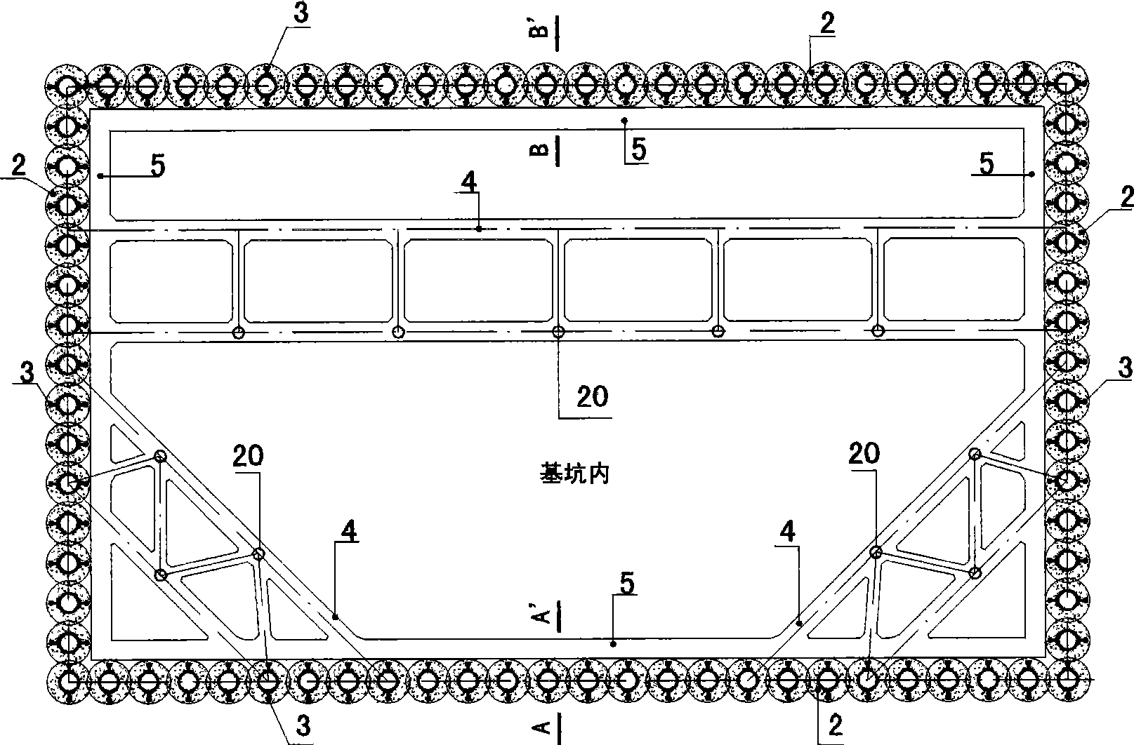
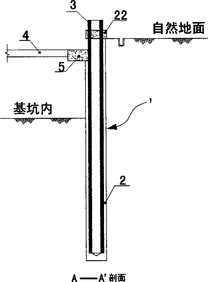
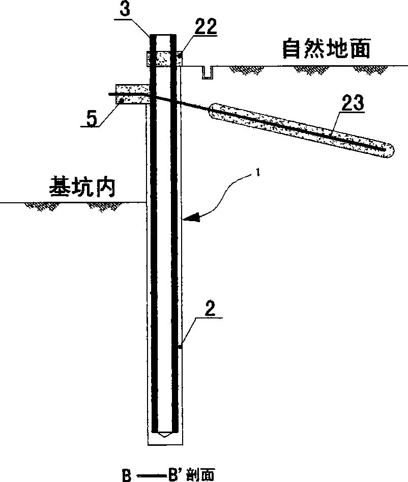
[0041] exist figure 1 , figure 2 , image 3 In the embodiment, when the rail beam cement-soil pile wall support structure is selected to adopt non-perfusion, cement-soil mixed in situ, the construction method of the present invention is:

[0042] 1. First, on the wall of the foundation pit, use a cement-soil mixing pile machine to stir the hole, and at the cement slurry mixing station, prepare the cement slurry according to the optimized proportion of the cement slurry provided by the laboratory, and then mix the prepared The cement slurry is transported to the cement-soil pile-forming mixer with a delivery pump, and the cement-soil pile-forming mixer makes a series of cement-soil piles in the stratum, and then, according to the rail provided in Figure 4, Figure 5, Figure 6, Figure 7, and Figure 8 The beam structure...

Embodiment 2

[0047] Embodiment 2: An embodiment in which poured, non-in-situ mixed cement-soil is selected as the cement-soil pile wall support structure of the rail beam.

[0048] exist figure 1 , figure 2 , image 3 In the embodiment, when the cement-soil pile wall support structure of the rail beam is selected to use poured, non-in-situ mixed cement-soil, the construction method of the present invention is: ① The construction process of the pile wall is: prefabricated rail beam 1. Brush the release agent on the surface of the beam, machine the hole, hang the rail beam into the hole, mix and transport the cement soil on site, pour the cement soil to the hole, and complete the pile formation; ②The construction process of rail beam removal is: a , When using commonly used ointment-like release agent, directly pull out the rail beam and lift it away. b. When the surface of the rail beam is painted with a solid hot-melt mineral wax release agent, when the rail beam is pulled out, the on-...


PUM


Abstract

The invention provides a support structure for a rail beam cement-soil pile-wall to form an underground continuous wall for the support of foundation pits and side slopes. The support structure is composed of rail beam cement-soil pile support components in a continuously occluded arrangement form and support components in the foundation pits or pit wall anchor components. The rail beam is composed of a rail, a rail supporting component for supporting rails between rails, a connection flange in beam end bolts, a heat circulating reflux component attached to the inside of the beam and release agent paint to rail beam surfaces. The pile wall support components have the advantages of large buckling strength and stiffness, small wall deformation, flexible soil-cement pile material ratio, even mixing, convenient, flexible and fast construction, easy recovery of rail beams, low cost, no pollution, etc. The invention can be widely used in foundation pit and side slop support and protection works.

Description

technical field [0001] The invention relates to the field of pile wall support for foundation pits and side slopes in civil engineering. Background technique [0002] In the existing known technology, the SMW construction method (that is, the H-shaped steel cement-soil pile wall support structure) has been widely used in civil engineering at home and abroad. This kind of support structure realizes the support function of the foundation pit slope and other slopes in this way, that is, a special drilling mixer equipped with a stirring mechanism is used to drill holes in the formation, and the tip of the drill pipe is used to The cement slurry is injected, mixed with the in-situ soil in the formation forcibly, and a series of cement-soil row piles are formed in situ. Before the cement-soil row piles are solidified, H-shaped steel is inserted, and after solidification, a load-bearing and It is a composite structure of underground diaphragm wall with pile column type that can pr...

Claims


Application Information

Patent Timeline
Patent Type & Authority Applications(China)
IPC IPC(8): E02D17/20E02D5/20E02D17/04
Inventor 袁建标
Owner 袁建标
Why Eureka
Try Eureka