
Large caliber aspheric surface measuring apparatus and method based on ultra-precise revolving scanning

A measuring device, ultra-precise technology, applied in the direction of measuring devices, optical devices, instruments, etc., can solve the problems of low measurement speed, high motion accuracy requirements, and reduce the detection accuracy of the measured aspheric surface contour, so as to improve the contrast, The effect of increasing the measurement resolution

Inactive Publication Date: 2009-03-04
HARBIN INST OF TECH
View PDF0 Cites 60 Cited by
  • Summary
  • Abstract
  • Description
  • Claims
  • Application Information

AI Technical Summary

Problems solved by technology

The main disadvantages of this method are: it is difficult to manufacture the compensation lens; for different workpieces to be measured, different compensation devices must be made, which greatly increases the measurement cost, reduces the efficiency, and has poor applicability; the interferometer produced by ZYGO is currently the most recognized by various countries. Representative full-aperture interferometer products
This method is a fast-developing measurement technology for large-aperture aspheric surfaces in recent years. This technology overcomes the inability of traditional interferometers to measure the surface profile information of large-aperture aspheric surfaces, and also overcomes the shortcomings of not being able to measure large numerical aperture optical elements.
The main disadvantages of this technology are: high requirements on the movement accuracy of the movement mechanism, the process of aperture splicing will cause error transmission, thereby reducing the detection accuracy of the entire measured aspheric surface profile, and the measurement speed is low
But its main disadvantage is that the scanning beam is a double thin beam separated from each other, which is not robust to the measurement environment noise, such as temperature drift and air disturbance at the measurement site; the scanning head can only sense the For one-dimensional inclination information, if the three-dimensional measurement of the measured profile is realized, corresponding moving optical devices must be added, such as thick flat glass, Dove prism, etc. Gradient information is collected

Method used


Image

  • Large caliber aspheric surface measuring apparatus and method based on ultra-precise revolving scanning
  • Large caliber aspheric surface measuring apparatus and method based on ultra-precise revolving scanning
  • Large caliber aspheric surface measuring apparatus and method based on ultra-precise revolving scanning

Examples


Embodiment 1

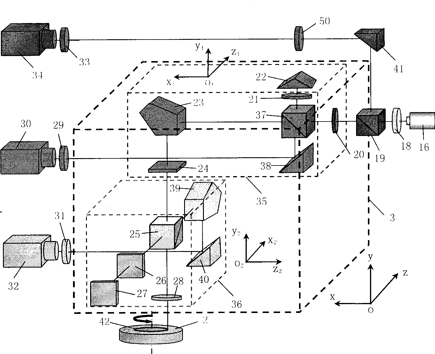
[0046] Adjust the beam splitter 37 so that the measurement light spot received by the CCD camera 30 is completely separated from the reference light spot; adjust the polarization beam splitter 25 so that the measurement light spot received by the CCD camera 32 is completely separated from the reference light spot; The spectroscope 25 is fixed, and then the component is calibrated, and after calibration, the component will not be adjusted in the subsequent rotary scanning measurement process. Adjust the linear polarizer 28 and the λ / 2 wave plate 24 so that the measurement and reference spot peak values ​​received by the CCD camera 32 of the sub-scan head 36 are approximately equal, and are approximate to the measurement light spot peak values ​​received by the CCD camera 30 of the sub-scan head 35 Equal; adjust the linear polarizer 21 so that the measured and reference spot peaks received by the CCD camera 30 of the sub-scanning head 35 are approximately equal. Adjust linear po...

Embodiment 2

[0049] see figure 2 And Fig. 9, rectangular prism 22 also can adopt plane mirror 49, by Figure 9A It can be seen that in order to compensate the inclination measurement error caused by the angular drift in the sub-scanning head 35, it is necessary to subtract the reference signal from the measurement signal, see Figure 9B , in order to compensate the inclination measurement error caused by the vibration of the beam splitter 37 in the sub-scanning head 35, it is necessary to add the reference signal to the measurement signal. In this case, the propagation path of the light beam in the sub-scanning head 36 does not change, and does not affect its error compensation method and measurement results.

Embodiment 3

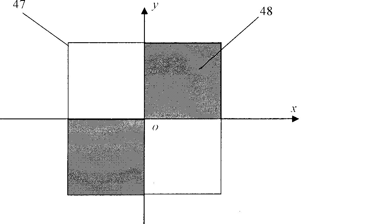
[0051] see figure 1 with Figure 10 , the linearly polarized He-Ne laser can also be a semiconductor laser, and after being collimated and thinned by a single-mode fiber collimating system, it is incident on the two-dimensional phase plate 18. The other components and working principles of this embodiment are the same as in Embodiment 1. same.


PUM


Abstract

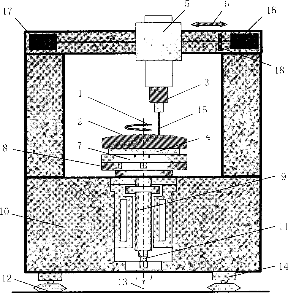
The invention provides a large diameter aspheric measuring device based on ultra-precision rotary scan and a method, belongs to the macroscopic measuring technology. The device comprises an ultra-precision air flotation turntable, a precision angle and angle measuring system, an ultra-precision linear air flotation guide, a length-measuring device and a gradient measurement system. The gradient measurement system comprises a linear polarization He-Ne laser or a semiconductor laser, a diffraction element, a scanning head and an image receiving unit. The linear polarization He-Ne laser or the semiconductor laser and the image receiving unit are separately fixed on the two sides of the base beam. The scanning head is fixed on the ultra-precision linear air flotation guide. The scanning head comprises a radial gradient measurement sub-scanning head and a tangential gradient measurement sub-scanning head, both of which comprise an error compensation light path. The working platforms of the two sub-scanning heads are orthogonal to each other. The invention discloses a large diameter aspheric measuring method based on ultra-precision rotary scan.

Description

technical field [0001] The invention belongs to a profile measurement device and method, and mainly relates to a large-diameter aspheric macro-profile measurement technology. Background technique [0002] Compared with spherical optical parts, aspheric optical parts have more design freedom, which can not only effectively correct advanced aberrations in the optical system, significantly improve the imaging quality of the optical system, but also significantly simplify the structure of the optical system and expand the functions of the optical system. Therefore, aspheric mirrors have been widely used, and the advantages of various large-diameter aspheric surfaces are more prominent and the demand is more urgent. [0003] During the processing of aspheric optical elements, it is very important to accurately measure their surface shape: in a sense, there are no high-precision detection methods and instruments that are compatible with the processing accuracy, and the precision a...

Claims


Application Information

Patent Timeline
Patent Type & Authority Applications(China)
IPC IPC(8): G01B11/24
Inventor 谭久彬郎治国刘俭
Owner HARBIN INST OF TECH
Learn More