Multi-stag ion fluidizing device and method

A jet device and multi-stage technology, which is applied in the field of multi-stage ion jet devices, can solve the problem of not being able to provide a propeller that meets the requirements, and achieve the effects of increasing the amplitude, increasing the efficiency and increasing the power.

Inactive Publication Date: 2009-03-11
SHANGHAI JIAO TONG UNIV
View PDF1 Cites 19 Cited by
  • Summary
  • Abstract
  • Description
  • Claims
  • Application Information

AI Technical Summary

Problems solved by technology

The above-mentioned documents clearly cannot provide propellers meeting such requirements

Method used


Image

  • Multi-stag ion fluidizing device and method

Examples


Embodiment 1

[0035] A kind of ion jet method, concrete steps are:

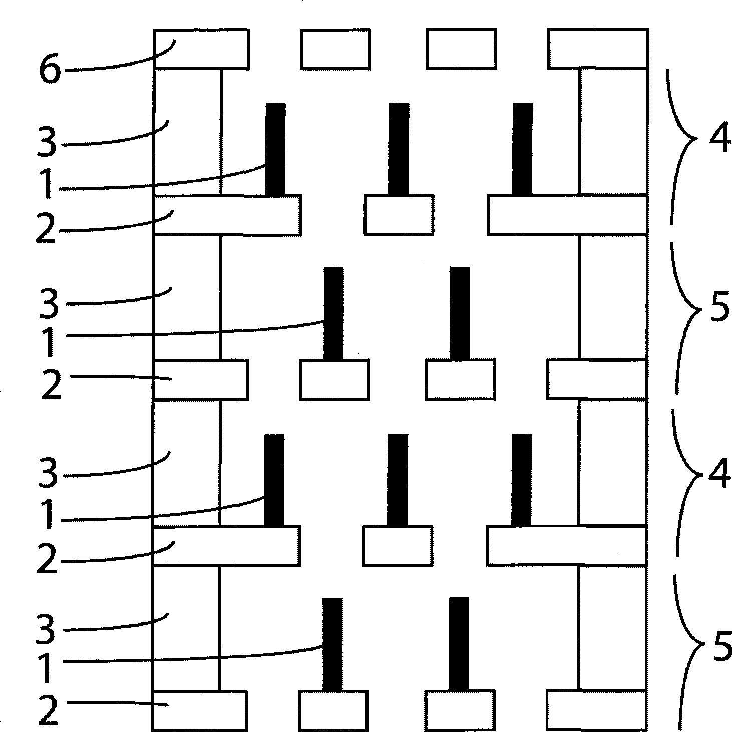
[0036] first step, such as figure 1 As shown, a multi-stage ion jet structure is formed, the number of stages is four, each accelerating electrode constitutes one stage, and each accelerating electrode is composed of a silicon wafer, and multiple first accelerating electrodes and second accelerating electrodes are arranged alternately, The final structure is formed by "silicon oxide-silicon oxide" bonding. The structure of the multi-stage ion jet device involved in this embodiment is as follows:

[0037] Including the first accelerating electrode 4, the second accelerating electrode 5 and the end hollow electrode 6, the first accelerating electrode 4 and the second accelerating electrode 5 are alternately arranged to form a multi-level electrode structure, every two adjacent first accelerating electrodes 4 and Between the second accelerating electrodes 5, an insulating layer is arranged so that the two are insulated from ...

Embodiment 2

[0046] A kind of ion jet method, concrete steps are:

[0047] first step, such as figure 1 As shown, the structure of the multi-stage ion jet device is as in Example 1.

[0048] In the second step, the loading voltages on the accelerating electrodes at each level are 100V, 75V, 50V, and 25V respectively, and the hollow electrodes at the end are grounded. The test is carried out in a vacuum chamber, the gas in the vacuum chamber is normal pressure air, which is pumped to 10 -4 The air pressure of Pa, through the air inlet of the vacuum chamber, a flexible gas supply channel is set to connect with the entrance of the ion jet device, and the gas sent in is N 2 Gas, the flow velocity is 5.1m / s, the flow velocity of the outflow gas is 12.4m / s, the mass flow velocity is 0.031g / s, after measurement, the thrust is about 230 micronewtons.

[0049] Examples 1 and 2 illustrate that the technical solution provided by the present invention can output a thrust of tens of micronewtons und...

Embodiment 3

[0051] A kind of ion jet flow method to generate air flow under normal pressure, its specific steps are:

[0052] first step, such as figure 1 As shown, the structure of the multi-stage ion jet device is as in Example 1.

[0053] In the second step, the loading voltages on the accelerating electrodes at each level are 200V, 150V, 100V, and 50V respectively, and the hollow electrodes at the ends are grounded. The test is carried out in air at normal pressure. During the test, the device is installed on the slide rail and moves at a speed of 0.001m / s in a direction parallel to the test platform. The flow velocity is 9.3m / s, and the mass flow velocity is 0.079g / s.

[0054] Compared with a conventional ion wind generating device, this device is composed of a needle-shaped electrode corona discharge structure with a gap of 350 microns and a needle tip with a minimum diameter of 20 microns. Its relatively stable operating voltage is between 4200-4900V. The velocity of the ion win...


PUM


Abstract

The invention discloses a multi-step typed ion jet device and a method, belonging to the fields of aerospace technology and microelectronic technique; the device comprises a first accelerating electrode, a second accelerating electrode, and an end hollow electrode; the first accelerating electrode and the second accelerating electrode are alternatively arranged so as to form a multi-step electrode structure; an insulation layer is arranged between every two adjacent first accelerating electrode and second accelerating electrode so as to lead the first accelerating electrode and the second accelerating electrode to be insulated with each other; the method utilizes the electric field convergence effect of polarized electrode array tip part, reinforces the electric field strength of region adjacent to the electrode, thus ionizing the gas molecular of adjacent area; the multi-step ion jet device structure is adopted and voltage is applied on the structure, thus forming ion jet. The device and the method can improve the ionization efficiency, reduce the working voltage, and work under the environment of multi-gas-plasma.

Description

technical field [0001] The present invention relates to an ion jet device and method in the fields of aerospace technology and microelectronics technology, in particular to a multi-stage ion jet device and method. Background technique [0002] The role of ion propulsion in aerospace technology is very important. Compared with solid or liquid chemical rockets, ion propulsion has ten times higher efficiency, ten times greater specific impulse, and ten times higher effective ejection velocity, and has a long Although the thrust produced by chemical rockets is several orders of magnitude higher than that of ion thrusters, the above characteristics make ion thrusters more adaptable in the long-distance space flight of aircraft and the fine adjustment of attitude and orbit. This is because, due to the higher efficiency and longer running time of ion propulsion, although its thrust is small, the instantaneous acceleration is small, so that the aircraft cannot reach the speed that c...

Claims


Application Information

Patent Timeline
Patent Type & Authority Applications(China)
IPC IPC(8): B64G1/40
Inventor 侯中宇蔡炳初
Owner SHANGHAI JIAO TONG UNIV
Why Eureka
Try Eureka