Check patentability & draft patents in minutes with Patsnap Eureka AI!

microwave position detector

A detector and microwave technology, applied in electrical and related fields, can solve the problems of no effective and practical example of position detection, difficulty in implementation, high cost, etc.

Inactive Publication Date: 2011-12-28
BEIJING KAIMEN CONTROL ENG INST
View PDF0 Cites 0 Cited by
  • Summary
  • Abstract
  • Description
  • Claims
  • Application Information

AI Technical Summary

Problems solved by technology

The former is difficult to obtain accurate measurement values ​​due to the slipping phenomenon between the moving object and the track or the ground; the disadvantages of the latter two are that the system is complicated, the cost is high, and the position detection accuracy is also limited
[0003] In the current literature on microwave position detectors, the way to detect the position of moving objects is based on changes in microwave power, microwave frequency or phase, which is very technically difficult to implement, and the cost of equipment is difficult to control
When using the Doppler principle to detect the position of a moving object, the measurement accuracy will be deteriorated due to signal noise and close-range reflectors. In addition, because this principle detects the moving speed of the object, its position is obtained through cumulative calculation. It is not the absolute value position of the measurement, so there is a possibility of poor accuracy and data loss in actual use
In short, there are no effective and practical examples of using microwave technology to detect the position of linear mobile equipment in factories and enterprises.

Method used


Image

  • microwave position detector
  • microwave position detector
  • microwave position detector

Examples


Embodiment Construction

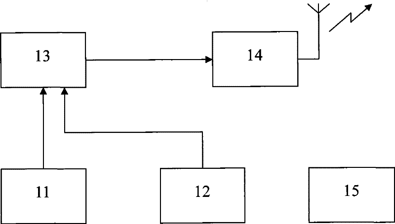
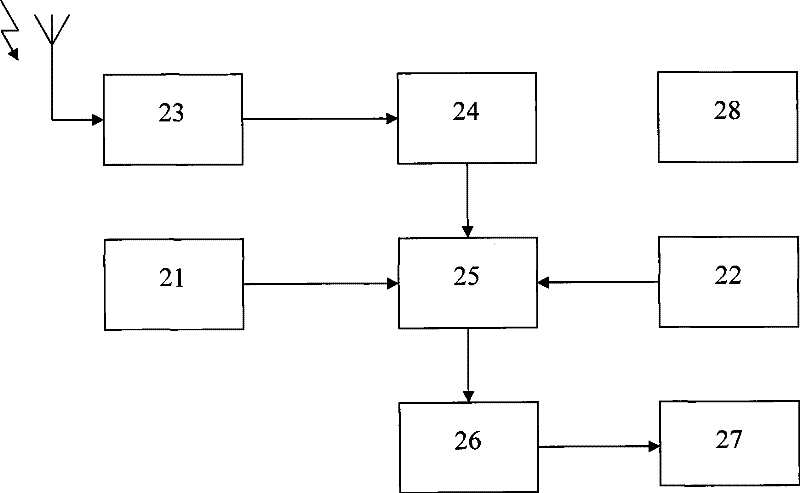
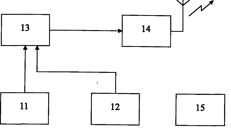
[0008] The microwave position detector is composed of a microwave transmitting device and a microwave receiving device. figure 1 is the functional block diagram of the microwave transmitting device, figure 2 It is a functional block diagram of a microwave receiver.

[0009] figure 1 The working principle of the microwave transmitting device is as follows: the real-time clock signal is generated by the clock signal generator 11, and its minimum unit is nanosecond, and the clock signal is sent to the modulator 13; the modulation time cycle controller 12 controls the modulation time of the fixed cycle, and the cycle time can be Adjustment, optional within the range of 0.001 milliseconds to 1 millisecond, the position detection accuracy for the mobile device when the speed is 120 m / min is 0.002 to 2 mm; the modulated clock signal pulse train is emitted by the microwave transmitter 14, and the transmitted The frequency is between 300MHz and 300GHz, which can be selected accordin...


PUM


Abstract

The microwave position detector of the present invention belongs to electrical and related technologies, and aims to improve and enhance the position detection effect of current linear moving equipment by adopting modern microwave detection and control technology, and reduce equipment and construction maintenance costs. The main point is that the microwave position detector is composed of a microwave sending device and a microwave receiving device, which respectively send and receive the clock carrier signal generated by the modulation time period controller (12) and the modulator (13); adopt the clock synchronization controller (22) Realize the clock synchronization between the clock signal generator (11) of the microwave sending device and the clock signal generator (21) of the microwave receiving device, obtain the precise microwave transmission time through the clock signal comparator (25), and then calculate the level of the measured object The moving distance and instantaneous speed have the advantages of high reliability, good detection accuracy, simple system implementation, and low equipment cost. speed detection.

Description

technical field [0001] The invention belongs to electrical and related technologies. Background technique [0002] For the position detection of linear mobile equipment such as factory cranes and various transport trolleys, photoelectric encoders, induction wireless positioning systems, radio frequency induction identification systems and other detection methods are mostly used at present. The former is difficult to obtain accurate measurement values ​​due to the slippage between the moving object and the track or the ground; the disadvantages of the latter two are that the system is complicated, the cost is high, and the position detection accuracy is also limited. [0003] In the current literature on microwave position detectors, the way to detect the position of moving objects is based on changes in microwave power, microwave frequency or phase, which is very technically difficult in terms of specific implementation, and the cost of equipment is difficult to control. Wh...

Claims


Application Information

Patent Timeline
Patent Type & Authority Patents(China)
IPC IPC(8): G01B15/00G01P3/64
Inventor 高毅夫
Owner BEIJING KAIMEN CONTROL ENG INST
Features
  • R&D
  • Intellectual Property
  • Life Sciences
  • Materials
  • Tech Scout
  • Unparalleled Data Quality
  • Higher Quality Content
  • 60% Fewer Hallucinations
Learn More